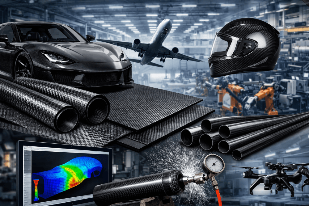
Marine and underwater engineering projects push materials to their limits. High pressure, complex geometries, sealing requirements, and zero-failure tolerance make these applications very different from traditional automotive or consumer composites.
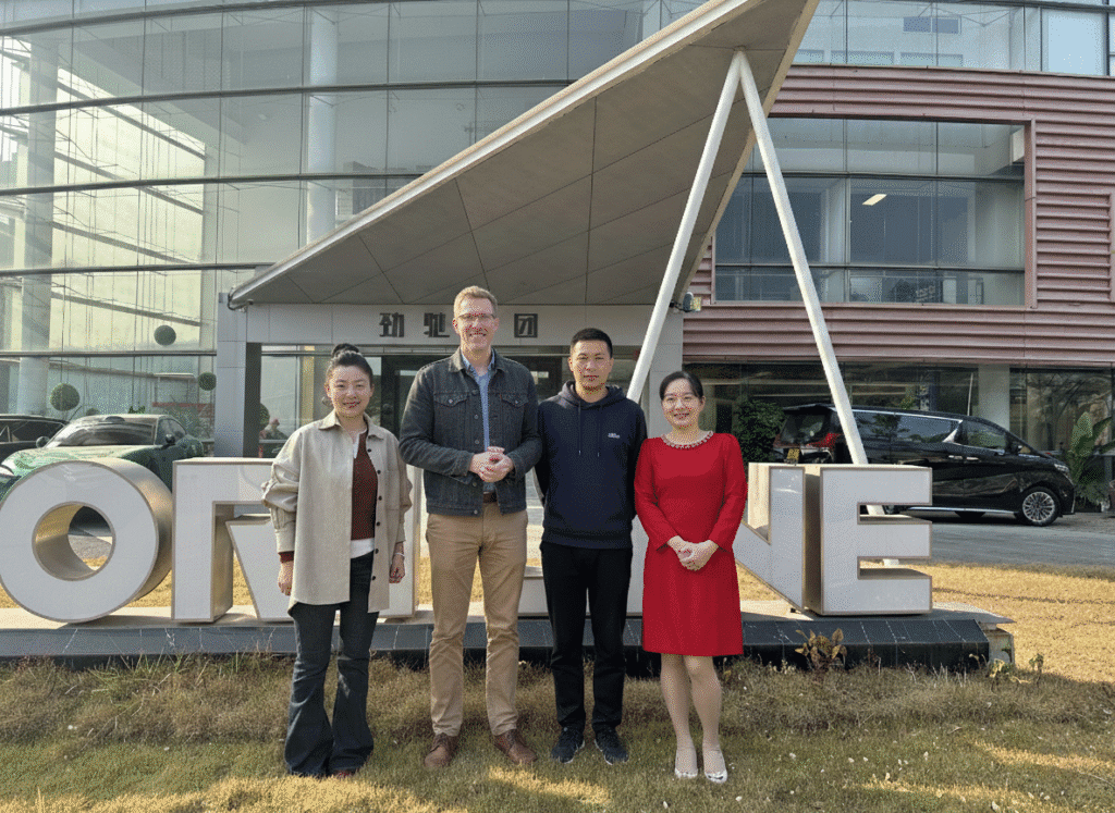
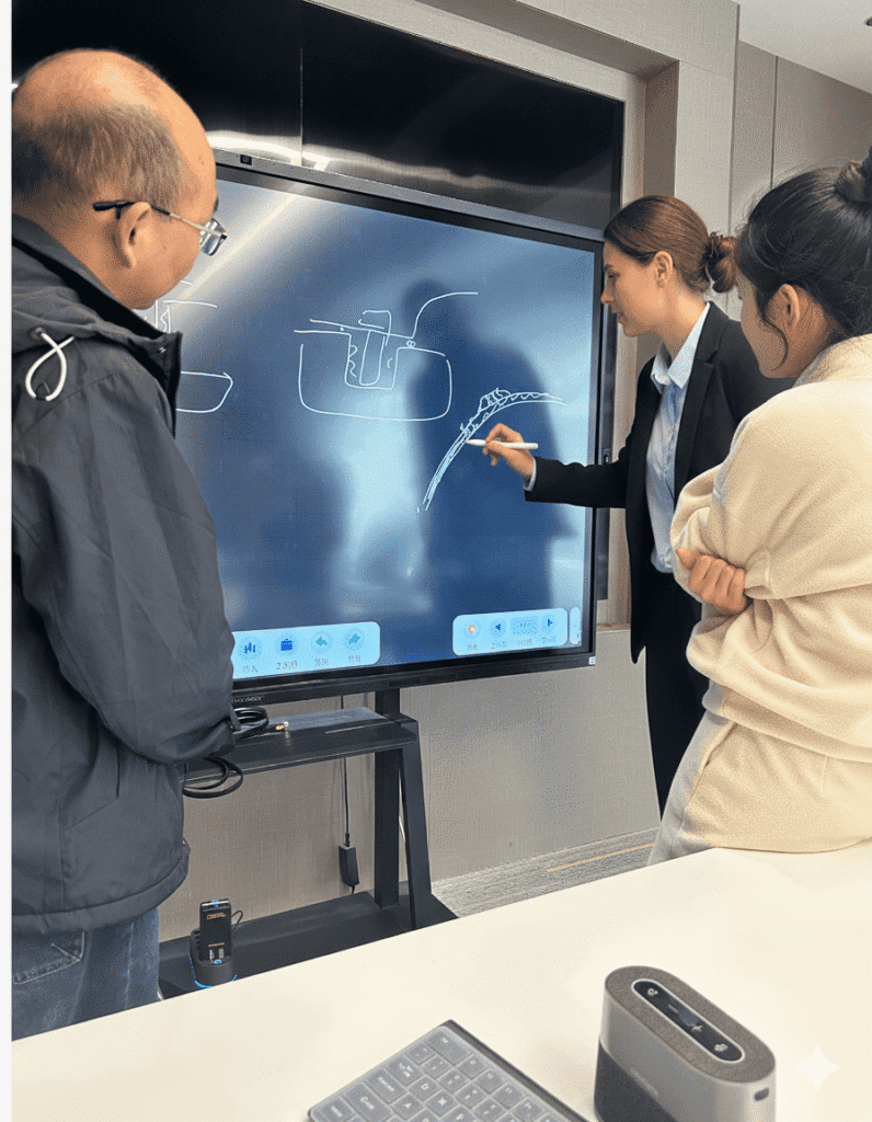
Earlier this week, we hosted a client working in mechanical engineering, chamber design, and underwater/marine applications. Their product requires pressure resistance, leak-proof reliability, and structural continuity — all under extreme safety conditions.
This article documents the visit as a real engineering breakdown:
how we assess feasibility, how we communicate risk, how we design molds and layups, and how we move from concept → prototype → mass production.
1. Understanding the Client’s Marine & Underwater Requirements
A Safety-Critical Application Under Extreme Pressure
The client’s project involves a pressure-bearing headgear/chamber product designed for underwater environments. Unlike automotive components, these structures must remain stable in high hydrostatic pressure while ensuring zero leakage. A single failure point could compromise safety or even threaten a diver’s life.
Because of this, our first discussion focused on:
- Pressure resistance
- Seam design
- Feasibility of one-piece molding
- Risk of delamination, voids, and weak points
- How structural loads travel through composite layers underwater
Carbon fiber is an outstanding choice for marine engineering due to its stiffness-to-weight ratio and corrosion resistance—but only when engineered with the correct mold strategy and layup architecture.
What the Client Needed From JCSPORTLINE
The client’s full product development scope included:
- Early concept validation
- Small-scale R&D prototypes
- A controlled testing phase for pressure, leakage, and structural integrity
- Transition to precision mass production

They wanted to understand how far carbon fiber could go, what risks exist, and which geometric shapes could be molded reliably.
2. Carbon Fiber Feasibility Analysis: Our Engineering Approach
Our feasibility analysis always answers two core questions:
1) Can the product be manufactured in carbon fiber safely?
2) If yes, what is the optimal mold and layup strategy for it?
During the meeting, three of the client’s core questions guided the discussion.
2.1 One-Piece Molding vs Multi-Piece Assembly
Client concern:
“This is a safety-critical product. Can it be made as a one-piece mold? If not, where are the seam lines?”
Our explanation:
For complex domes or headgear structures that must withstand pressure, a fully one-piece mold is often geometrically impossible or structurally suboptimal.
Instead, our engineers determine:
- Which regions can be molded as monolithic structures
- Which areas require mold segmentation due to draft angle or curvature
- Where seams can exist without compromising pressure resistance
- Whether fasteners or embedded inserts are required to secure multiple segments
- Whether internal reinforcement ribs or layup thickening is needed
We also clarified that “one-piece appearance” does not always mean “one-piece mold.”
Many marine-grade composite structures consist of two mirror molds that are later bonded via engineered layup continuity.
2.2 How a Seamless Structure Is Created: Mirror Molds + Interlocking Layups
Client question:
“If we use multiple molds, how does the final part look like one complete piece?”
We explained our approach:
- Many pressure vessels and dome-like structures use two mirrored molds
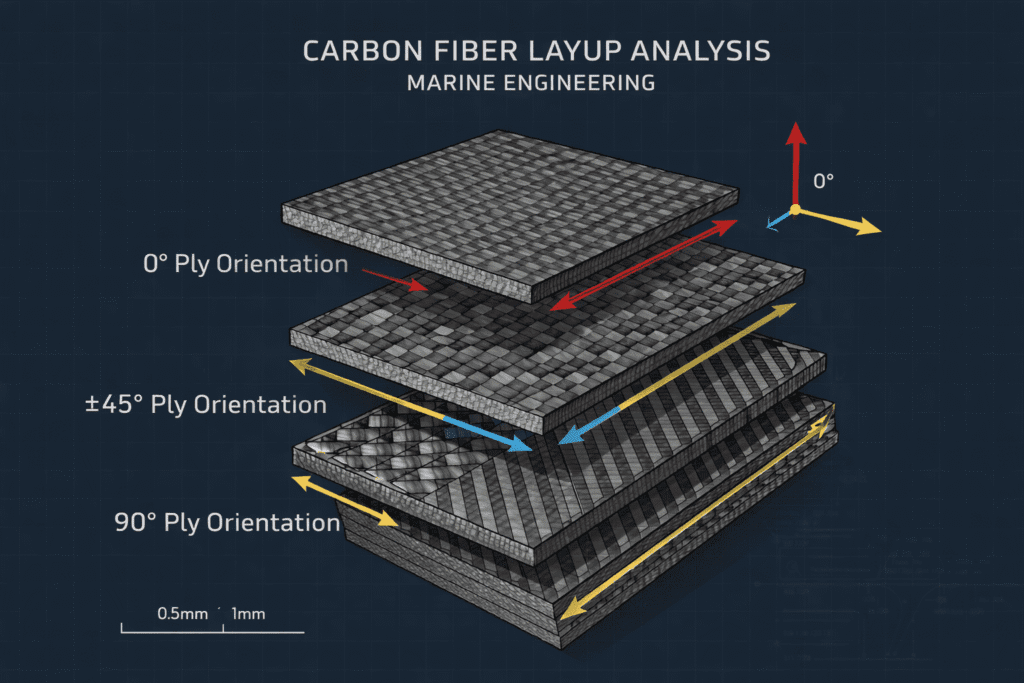
- Carbon fiber layers are placed in interlocking patterns
- Layup orientation varies: 0°/45°/90° for maximum pressure dispersion
- Structural bonding occurs during curing
- After demolding, the surface appears continuous and seamless
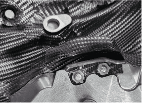
This reassured the client that multi-piece tooling does not mean visible seams or weak points — the final part behaves like a single integrated structure.
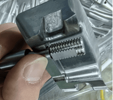
2.3 Embedded Hardware: Safe Fastening for Underwater Pressure
Client question:
“How do you fix two parts together? Screws? Inserts? Protrusions?”
We discussed three fastening strategies:
- Embedded metal inserts
- Placed during layup
- Offer strong sealing and load transfer
- Protruding carbon bosses
- Machined or molded
- Provide natural screw landing zones
- Hybrid reinforcement zones
- Carbon + metal integration
- Designed to avoid stress concentration or leakage risks


Safety-critical products require fastening logic that maintains sealing integrity — so we emphasized that every insert or screw seat must be reinforced with additional plys and sealing resin barriers.
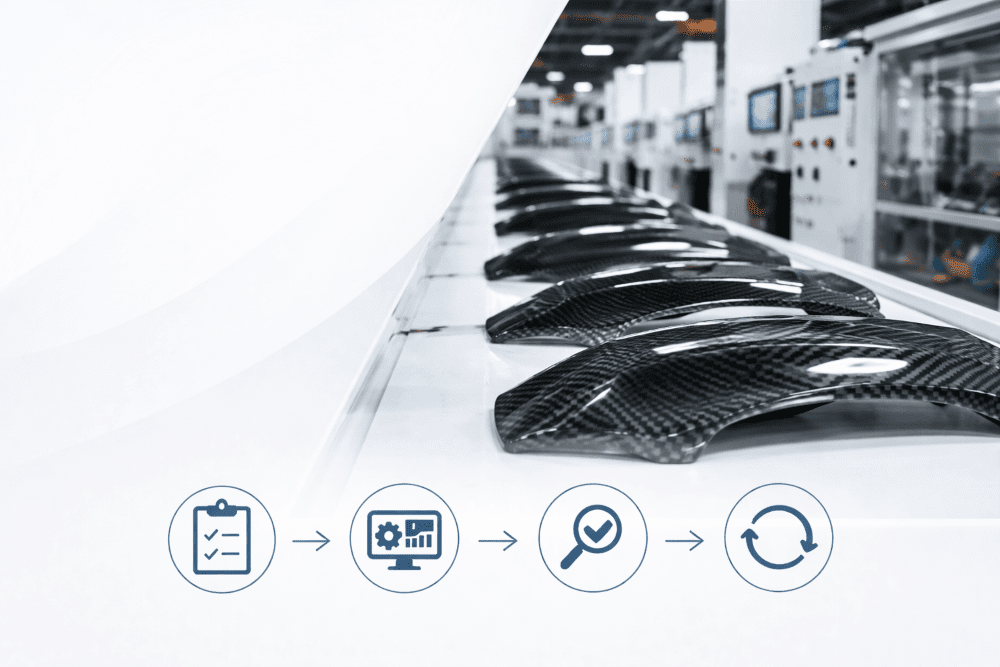
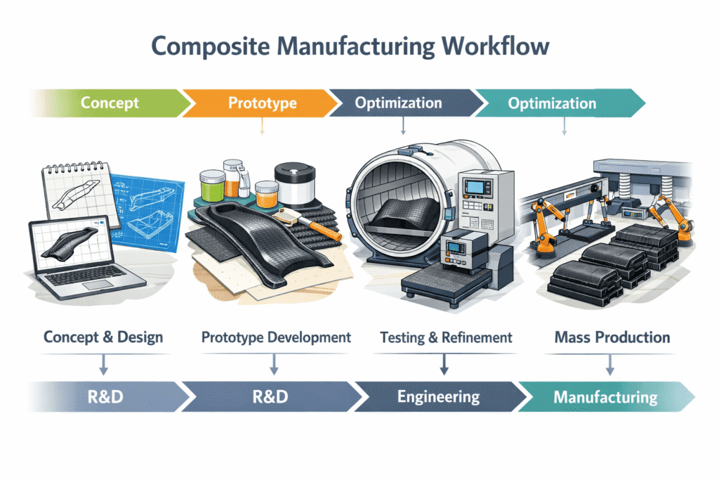
3. Prototyping & Testing Workflow: How We Move From Concept to Production
A major portion of the meeting focused on the project’s full RFQ (Request For Quotation) and execution flow.
3.1 Step 1 — Client Submits 3D Files for Feasibility Analysis
The client provides:
- STP/IGS/3MF files
- Functional requirements (pressure rating, target depth, etc.)
- Tolerances
- Planned testing standards
- Assembly interfaces
JCSPORTLINE then produces:
- A manufacturability review
- Mold segmentation plan
- Layup estimate (ply count, fiber directions)
- Risk assessment (pressure zones, stress points)
- Recommended prototype path
This first step helps ensure both sides understand what is realistic and safe.
3.2 Step 2 — Prototype Plan: Simplified Mold Before Full Production Tooling
Client concern:
“This product requires pressure testing. Can we make a simple mold first just to check geometry and basic performance?”
Absolutely — and we highly recommend it.
Simplified prototype mold goals:
- Validate overall shape and size
- Assess appearance and surface transitions
- Conduct preliminary pressure/deformation testing
- Confirm internal space and assembly logic
- Identify improvements before committing to expensive production molds
For marine engineering projects, skipping this stage increases risk unnecessarily.
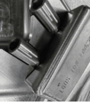
3.3 Step 3 — Precision Cutting for Complex Shapes: Our 5-Axis CNC Workflow
The client also asked:
“How do you cut non-flat shapes? If I need special openings or patterns, how do you do it?”
Our workflow uses:
- 5-axis CNC machining for multi-curved geometries
- CAD-CAM toolpaths generated directly from the 3D model
- Custom jigs and fixtures to stabilize irregular parts
- Inspection gauges to verify trimming accuracy
- Post-process sealing for any opening that interfaces with external hardware
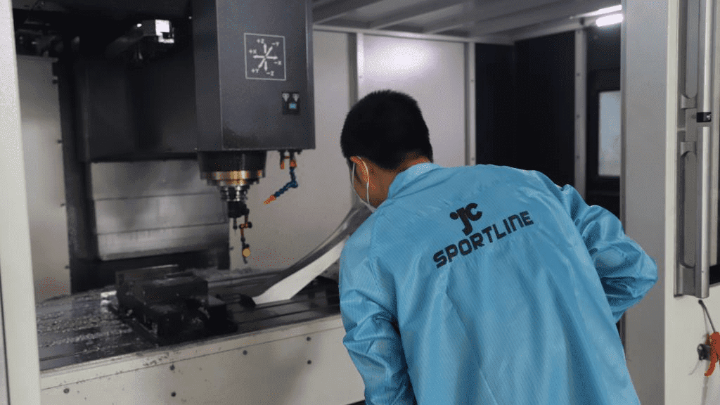
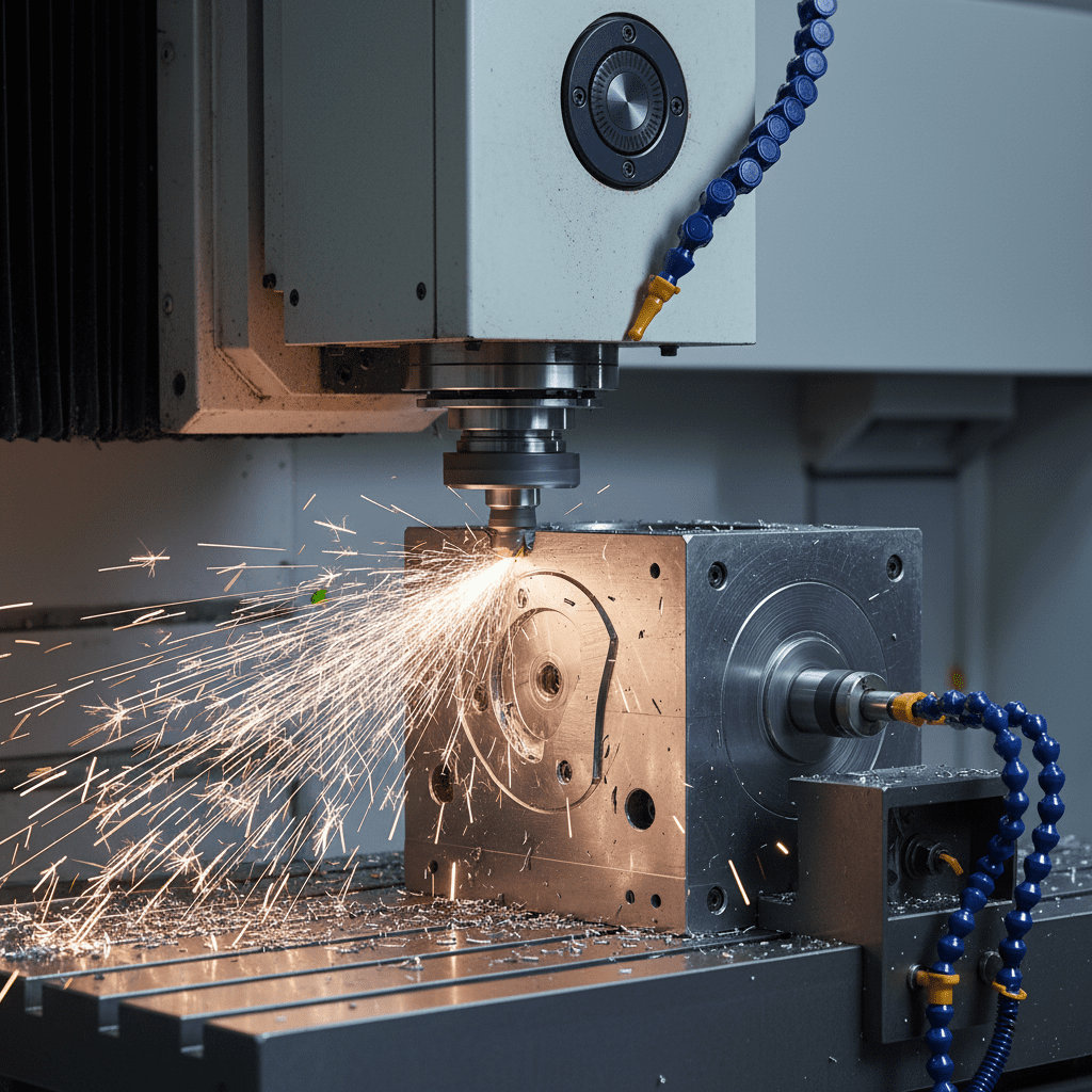
This reassured the client that accuracy is repeatable even for complex underwater geometries.
3.4 Step 4 — Production Mold + Mass Production Readiness
Once the prototype is validated, we transition to:
- Full production mold (P20 steel or high-grade aluminum, depending on volume)
- Final layup schedule
- Surface finish controls (gloss/matte, gelcoat or clear resin)
- Production QC plan:
- Fiber alignment checks
- Void content control
- Cure cycle validation
- NDT inspections (ultrasound/CT depending on customer need)
The client appreciated seeing the full roadmap from concept → prototype → true production reliability.
4. On-Site Interaction & Real Engineering Conversations
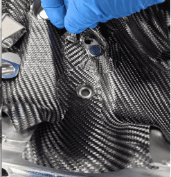
During the visit, we reviewed drawings, inspected previous samples, and examined areas where:
- Layup design must be thicker
- Safety-critical zones must be reinforced
- Mold parting lines must be relocated
- Hardware embedment must be optimized

We also walked the client through:
- Mold storage
- Autoclave and hot-press rooms
- 5-axis CNC workspace
- QC stations
- Surface finishing areas
This hands-on session helped the client visualize each step of the manufacturing journey and built mutual confidence.
5. FAQs: Common Questions About Carbon Fiber for Underwater Engineering
Q1. Can carbon fiber be safely used for underwater pressure vessels or chambers?
Yes — when designed with appropriate layup thickness, fiber orientation, and controlled seams. Incorrect layup or poor resin flow can compromise safety.
Q2. Can carbon fiber replace metal for deep-water products?
Not always.
Carbon fiber exceeds aluminum in many categories but metal may remain necessary for threaded interfaces or extreme-depth pressure housings. Hybrid solutions are often ideal.
Q3. How many prototypes are typically needed?
Usually 2–3 rounds:
- Simplified visual/functional prototype
- Structural prototype for testing
- Final pre-production validation
Q4. How long is the full project timeline from concept to mass production?
Depending on complexity: 8–16 weeks, including prototyping, testing, and tool development.
Final Thoughts
This client visit demonstrated what makes marine and underwater composite projects uniquely complex — and why carbon fiber feasibility analysis requires careful engineering, not guesswork.
From mold segmentation to layup optimization, from pressure-resistance logic to CNC precision cutting, JCSPORTLINE’s engineering workflow is built to support customers from early concept all the way to stable mass production.