For OEM engineers, procurement leaders, and supply chain managers, selecting a supplier capable of delivering a reliable carbon fiber roof box program requires a deep understanding of both engineering design principles and manufacturing processes. Large composite structures introduce unique technical challenges, including structural stiffness, dimensional accuracy, laminate consistency, and repeatable surface quality.
This article explains the complete engineering journey of a carbon fiber roof box—from early design considerations to prototype development and mass production—providing insight into how modern composite manufacturing transforms a concept into a scalable product.
Understanding the Engineering Requirements of a Carbon Fiber Roof Box
Designing a carbon fiber roof box is significantly more complex than manufacturing small carbon fiber trim parts. Because roof boxes are large exterior components mounted directly on vehicles, their design must balance structural strength, weight reduction, aerodynamic efficiency, and visual appearance.
Performance Requirements for Large Carbon Fiber Structures
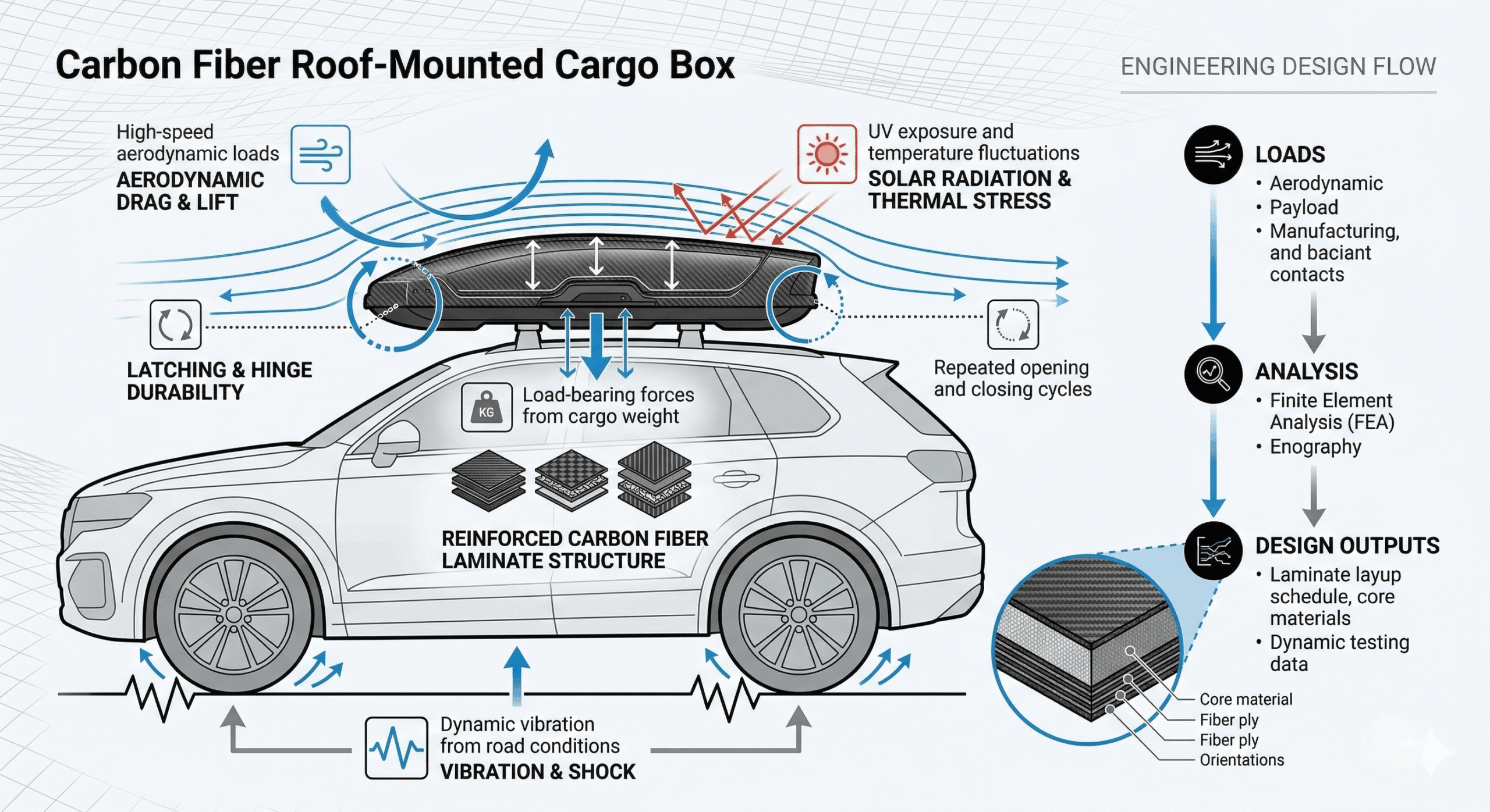
Roof-mounted cargo boxes must withstand a variety of real-world conditions:
- High-speed aerodynamic loads
- Dynamic vibration from road conditions
- UV exposure and temperature fluctuations
- Load-bearing forces from cargo weight
- Repeated opening and closing cycles
Unlike smaller components, the large surface area of a roof box makes it vulnerable to flexing and deformation if structural engineering is inadequate. Engineers must therefore carefully design laminate structures that deliver stiffness without unnecessary weight.
For automotive applications, structural targets typically include:
| Performance Factor | Engineering Requirement |
|---|---|
| Structural stiffness | Prevent deformation under aerodynamic load |
| Weight reduction | Lighter than ABS or fiberglass alternatives |
| Impact resistance | Protection from road debris and handling |
| Weather durability | UV, moisture, and temperature resistance |
Balancing these requirements is central to successful carbon fiber roof box engineering.
Structural Strength vs Weight Targets
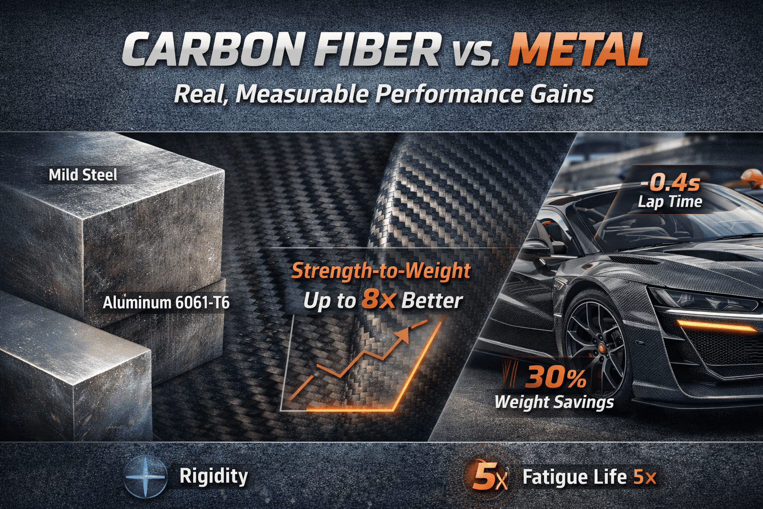
One of the primary advantages of carbon fiber is its exceptional strength-to-weight ratio. Compared with traditional materials like ABS plastic or fiberglass, carbon fiber composites can achieve significant weight reductions while maintaining superior stiffness.
Typical design targets include:
- 30–50% weight reduction compared to plastic roof boxes
- Structural stiffness sufficient to avoid deformation at highway speeds
- Reinforced mounting areas for roof rack attachment points
Achieving these targets requires precise laminate engineering, fiber orientation strategies, and material selection.
Aerodynamic Considerations for Roof-Mounted Cargo Systems
Roof boxes directly influence vehicle aerodynamics. Poor aerodynamic design can increase wind resistance, reduce fuel efficiency, and generate excessive noise.
Engineering teams typically evaluate:
- Airflow separation points
- Surface curvature and leading edge geometry
- Drag coefficient impact
- Wind noise generation
Advanced roof box development often integrates CFD (Computational Fluid Dynamics) simulations during early design stages to optimize aerodynamic performance.
Material Selection and Surface Finish Requirements
Beyond structural performance, appearance plays a crucial role in carbon fiber roof box design. OEM brands frequently use carbon fiber as a premium design element.
Common surface finish options include:
- Gloss carbon fiber for high-end automotive styling
- Matte carbon fiber for a motorsport aesthetic
- Raw carbon fiber texture for industrial applications
Interior surfaces must also be engineered to ensure bonding strength, durability, and long-term stability, particularly where structural adhesives or mounting hardware are used.
CNC Machining and Precision Mounting Points
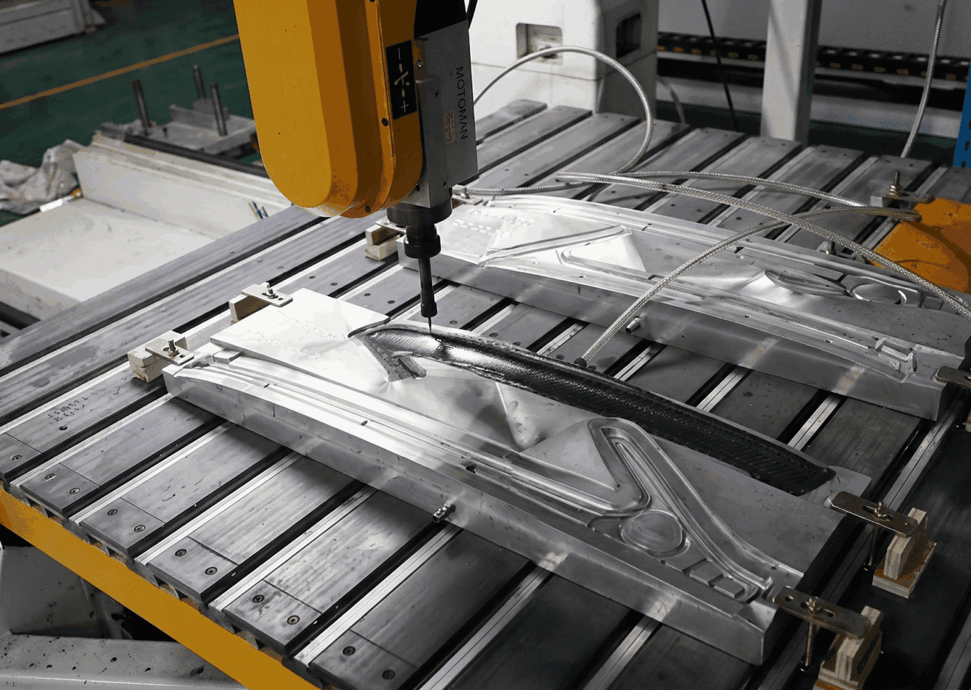
Roof boxes must align perfectly with vehicle roof rack systems. Precision drilling and mounting features are typically created using CNC machining after the composite curing stage.
This process ensures:
- Accurate mounting hole positioning
- Consistent dimensional tolerances
- Reliable fitment across production batches
For OEM programs, these engineering standards are essential before committing to full production tooling.
Material Selection and Carbon Fiber Weave Options
The appearance and structural behavior of a carbon fiber roof box are heavily influenced by the type of carbon fiber fabric and weave pattern used. Selecting the appropriate material requires balancing aesthetic goals with mechanical performance.
Common Carbon Fiber Weave Patterns
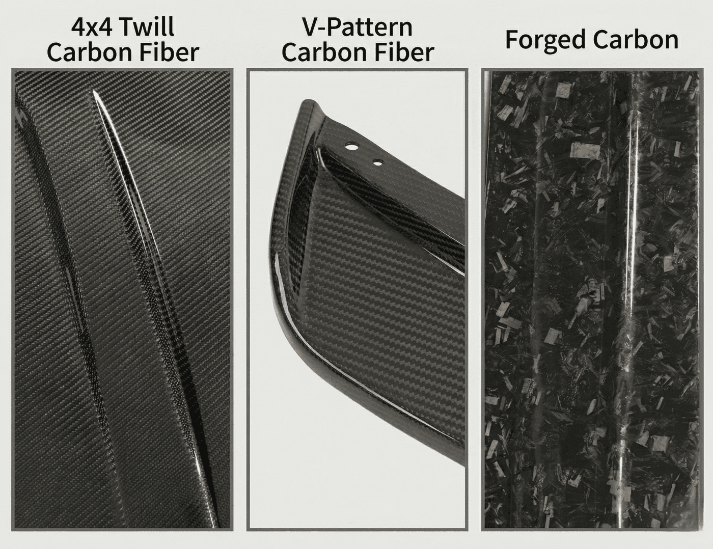
Several weave styles are commonly used in automotive composite components:
| Weave Type | Characteristics | Typical Use |
|---|---|---|
| 4×4 Twill Carbon Fiber | Smooth diagonal pattern with high visual appeal | Premium automotive accessories |
| Forged Carbon | Random fiber pattern with distinctive appearance | Luxury or high-performance styling |
| V-Pattern Carbon Fiber | Symmetrical weave alignment | Design-focused applications |
Among these, 4×4 twill carbon fiber remains the most widely used for roof boxes due to its ability to conform to curved surfaces while maintaining a premium appearance.
Carbon Fiber Grades
Carbon fiber fabrics are also categorized by filament count:
| Fiber Grade | Typical Application |
|---|---|
| 3K Carbon Fiber | Fine weave with premium appearance |
| 6K Carbon Fiber | Balanced strength and cost |
| 12K Carbon Fiber | Higher structural efficiency for large components |
Fabric weight typically ranges between 280–340 g/m², depending on the structural requirements of the component.
Aesthetics vs Structural Performance
While visual appeal is important for consumer-facing products, structural engineering must remain the priority.
Design trade-offs may include:
- Heavier structural fabrics for stiffness
- Decorative outer layers for visual consistency
- Hybrid laminate structures combining structural and cosmetic layers
Balancing these factors allows manufacturers to meet both brand positioning goals and engineering performance targets.
Laminate Structure and Strength Engineering
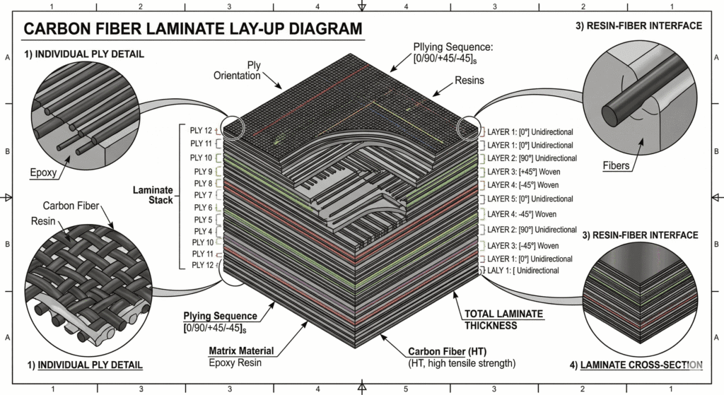
Carbon fiber parts derive their mechanical properties not only from the fibers themselves but also from the laminate stacking sequence.
Fiber Orientation Strategies
Composite laminates are typically arranged using multi-directional fiber layers to distribute loads effectively.
Common orientations include:
- 0° layers for longitudinal stiffness
- ±45° layers for shear strength
- 90° layers for transverse reinforcement
This multi-directional approach ensures the structure can withstand complex loading conditions.
Local Reinforcement Zones
Certain areas of a roof box require additional structural reinforcement:
- Mounting brackets
- Hinge attachment points
- Locking mechanisms
- Load-bearing base panels
Engineers often apply extra laminate layers or localized reinforcement patches to increase durability in these zones.
Kevlar Reinforcement for Impact Resistance
In some designs, Kevlar fiber layers are integrated within the laminate structure to improve impact resistance. Kevlar provides excellent toughness and can prevent cracking caused by sudden impacts.
Weight Optimization Through Laminate Engineering
One of the major benefits of composite engineering is the ability to optimize weight through precise laminate design. Engineers can remove unnecessary material while maintaining structural strength.
This approach results in lighter products without compromising safety or durability.
Prototype Development and Tooling Strategy
Before committing to large-scale production tooling, manufacturers typically conduct a prototype development phase.
Prototyping allows engineering teams to validate:
- Structural integrity
- Aerodynamic performance
- Manufacturability
- Assembly compatibility
For procurement teams, this stage reduces the financial risk associated with expensive tooling investments.
Prototype Manufacturing Methods
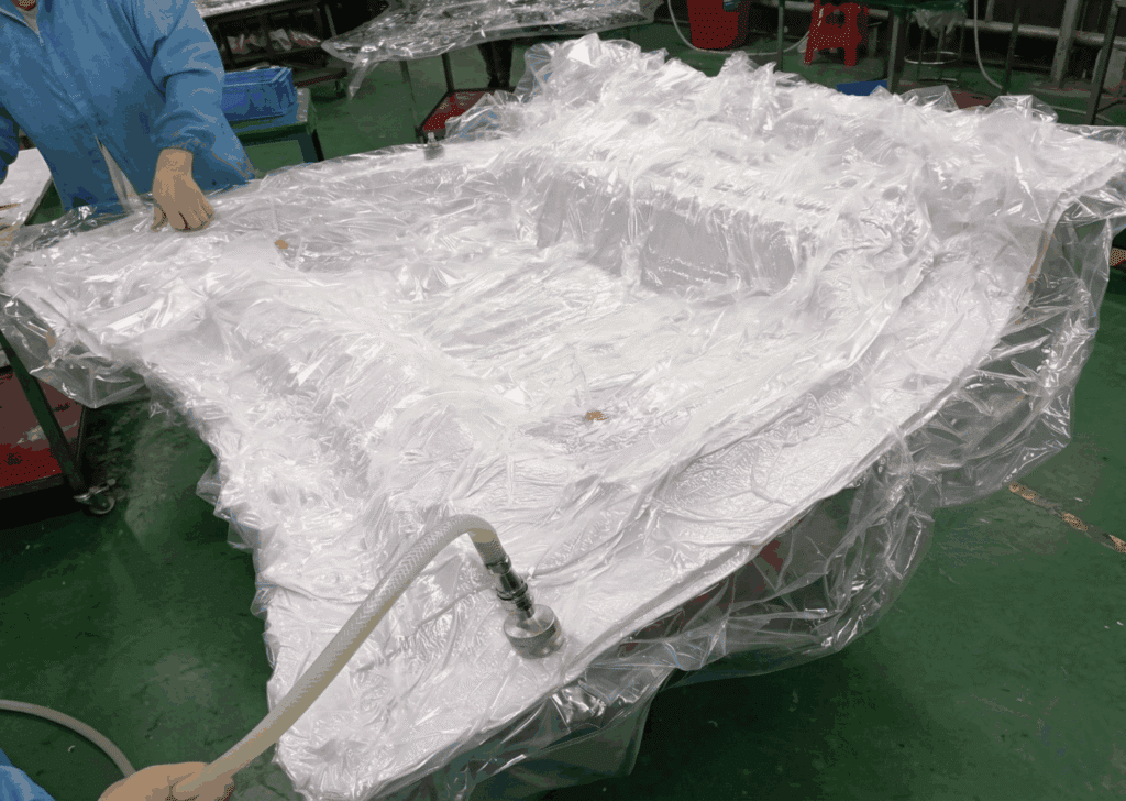
Early-stage carbon fiber prototypes are usually produced using vacuum bagging or vacuum infusion techniques.
These processes are ideal for small production runs because they provide good laminate consolidation without requiring complex tooling.
Typical prototype quantities range from 1–5 units, allowing engineers to test multiple design iterations.
Prototype testing may include:
- Structural load testing
- Aerodynamic evaluation
- Environmental durability testing
- Fitment verification
By validating these factors early, development teams can refine the design before moving to mass production.
Tooling Options for Carbon Fiber Roof Box Production
The selection of mold materials directly influences production efficiency, cost, and lifespan.
| Mold Type | Best Use Case |
|---|---|
| Epoxy molds | Low-volume production |
| Carbon fiber molds | Mid-volume manufacturing |
| Metal molds | High-volume compression molding |
Each tooling strategy offers different advantages in terms of durability and cost.
Selecting the correct tooling approach ensures that production capacity aligns with expected demand.
Scaling to Mass Production: Manufacturing Workflow
Once the prototype phase is complete, the project transitions into a scalable manufacturing workflow.
Large composite components like roof boxes require a carefully coordinated process involving:
- CNC machining
- Mold fabrication
- Composite layup
- Controlled curing cycles
- Final finishing and assembly
Maintaining consistency across these stages is essential for reliable mass production.
CNC Master Models and Mold Fabrication
The manufacturing process begins with the creation of a CNC-machined master model. This master serves as the reference surface for mold production.
Key factors include:
- Surface accuracy
- Dimensional stability
- Alignment precision
High-quality molds are critical for maintaining consistent part geometry across production batches.
Dimensional verification is typically performed before production begins to confirm that the molds meet engineering specifications.
Production Capacity and Scaling Strategy
Production capacity depends on several factors, including mold count, curing cycle time, and labor availability.
A single mold set may produce several units per day depending on the manufacturing process. For larger production programs, manufacturers often replicate molds to increase output.
Typical scaling strategies include:
- Multi-mold production cells
- Parallel curing processes
- Dedicated assembly stations
These approaches allow manufacturers to meet the volume requirements of OEM programs.
Quality Control and Supply Chain Reliability
Quality assurance plays a critical role in ensuring consistent product performance across large production runs.
Carbon fiber roof boxes must meet strict standards for:
- Structural performance
- Surface finish quality
- Dimensional accuracy
- Packaging durability
Robust inspection systems help maintain these standards throughout the production process.
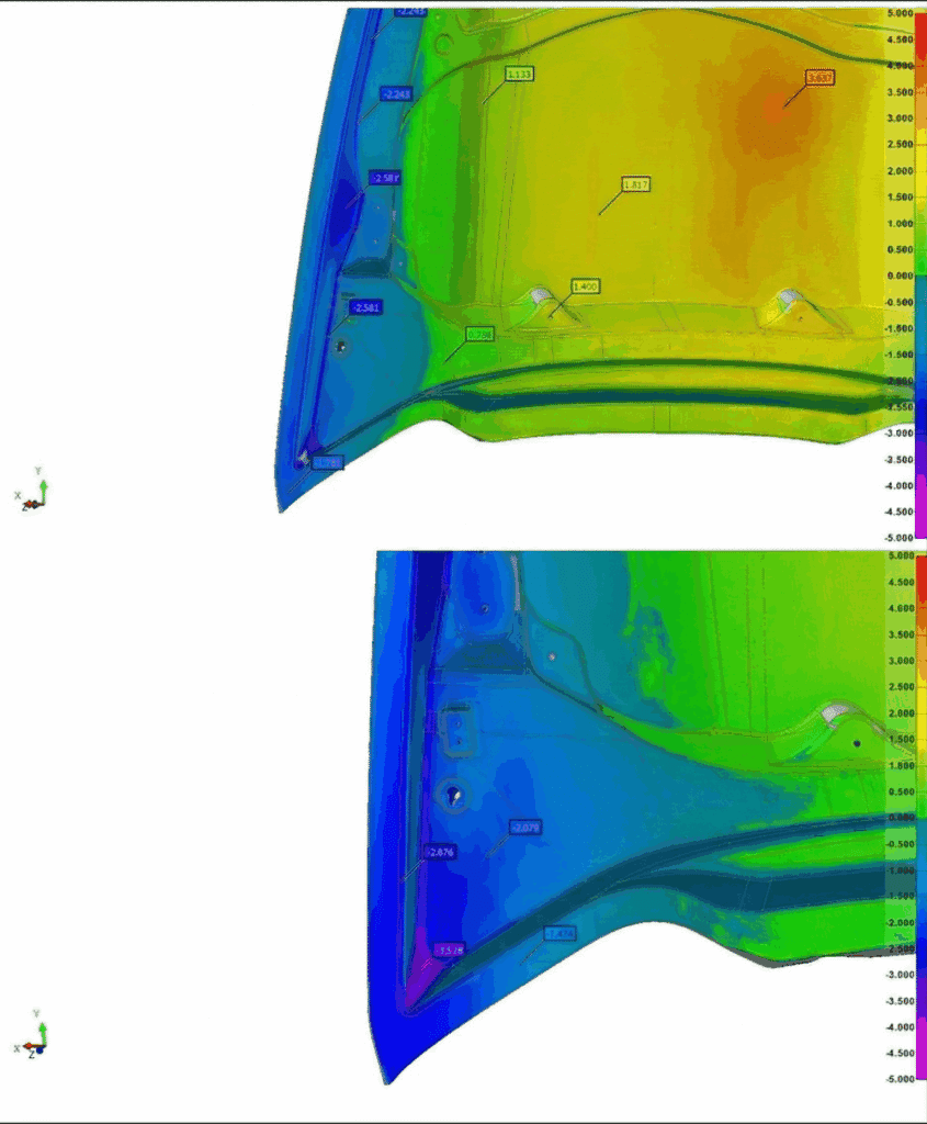
Dimensional Tolerance and Fitment Control
Dimensional tolerances are defined during the early engineering phase. These tolerances ensure that roof boxes fit correctly on vehicle roof rack systems.
Manufacturers typically use fixture-based measurement systems to verify part dimensions.
Continuous monitoring of mold condition also helps prevent dimensional drift over time.
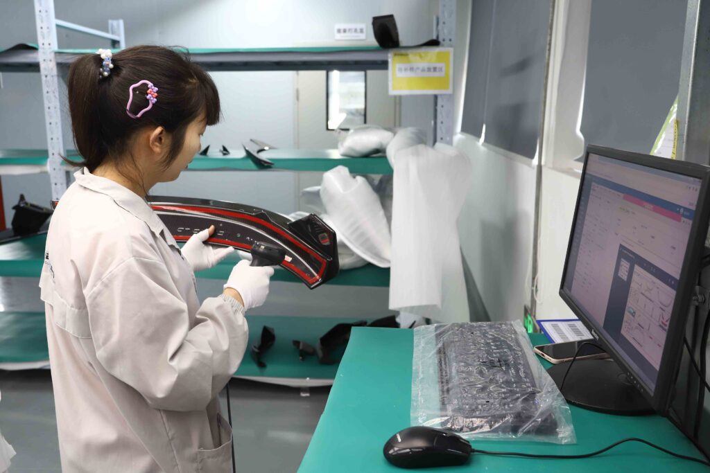
Inspection fittment Workflow Throughout whole molding and product production
Quality inspection occurs at multiple stages of the manufacturing process:
- CNC inspection stage — verifying master model accuracy
- Mold inspection stage — ensuring mold surface quality
- Prototype validation stage — confirming structural performance
- Batch production inspection — maintaining consistent quality
Regular inspection intervals allow manufacturers to detect potential issues before they affect large production batches.
Logo Application Accuracy and Inspection Fixture Control
In premium automotive accessories such as carbon fiber roof boxes, branding is not simply a cosmetic detail—it is a critical part of product identity and perceived quality. For OEM programs and branded aftermarket products, the accuracy and consistency of logo placement must meet strict visual and dimensional standards. Even minor shifts in logo alignment can negatively affect brand presentation and customer perception.
To maintain high standards in carbon fiber logo placement quality control, manufacturers typically integrate branding processes directly into the production workflow rather than treating them as a final cosmetic step.
Logo Application as Part of Exterior Finish Control
Carbon fiber roof boxes are often finished with high-end surface treatments such as gloss clear coats or matte carbon textures. Branding elements—whether sprayed logos, decals, or embedded badges—must be applied in a way that complements the surface finish and maintains visual symmetry.
Logo application methods may include:
- Precision spray painting for permanent logo integration
- High-quality decal application beneath protective clear coat layers
- Metal or composite badges bonded to designated mounting areas
These processes are typically performed after surface finishing but before final inspection, ensuring the branding integrates seamlessly with the overall exterior design.
Packaging Strategy for Large Carbon Fiber Roof Box Shipment
While manufacturing quality is critical, the final stage of the supply chain—packaging and transportation—plays an equally important role in protecting carbon fiber roof boxes before they reach customers.
Large composite components are vulnerable to damage during handling and shipping. Improper packaging can lead to surface scratches, edge impacts, or structural deformation, potentially negating the quality achieved during production. As a result, reliable suppliers integrate packaging design into the overall manufacturing strategy.
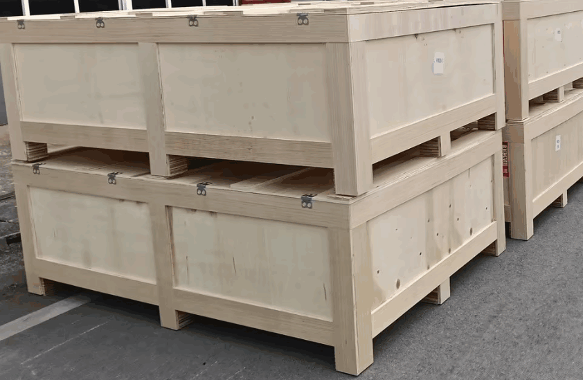
Common Packaging Methods for Carbon Fiber Roof Boxes
Two packaging methods are commonly used for exporting large carbon fiber automotive components:
| Packaging Type | Purpose |
|---|---|
| Single carton packaging | Provides lightweight protection for individual units |
| Outer wooden crate protection | Prevents compression damage during international shipping |
In many export programs, manufacturers combine both methods. Each roof box is first packed inside a reinforced carton, which is then secured within a wooden crate to withstand stacking pressure and handling during long-distance transport.
Packaging Design Based on Product Size and Surface Finish
Packaging requirements vary depending on the size and surface finish of the product. Carbon fiber roof boxes with high-gloss clear coats require additional protective measures to prevent cosmetic damage.
FAQ: Carbon Fiber Roof Box Development and Manufacturing
What is the typical development timeline for a carbon fiber roof box?
Development timelines vary depending on design complexity and tooling requirements. A typical project may include:
- Prototype development: 3–6 weeks
- Tooling fabrication: 4–8 weeks
- First production sample: 2–3 weeks
How Can Handcrafted Carbon Fiber Production Meet Customer Demand?
Production capacity depends on the size of the product and the number of molds used. Typically, one carbon fiber mold can produce about 10–30 units per month. To meet larger orders, manufacturers can replicate additional molds based on the customer’s delivery schedule, allowing production to scale while maintaining consistent quality.
How do manufacturers maintain dimensional consistency?
Manufacturers use precision molds, CNC-machined master models, and inspection fixtures to maintain consistent dimensions across production batches.
How are large carbon fiber components packaged for international shipping?
Roof boxes are typically packaged using:
- Protective foam inserts
- Reinforced export cartons
- Shock-resistant packaging materials
These measures help prevent damage during international transportation.