The Hidden Costs of Carbon Fiber Defects: Why Voids, Wrinkles & Delamination Matter—and How to Fix Them
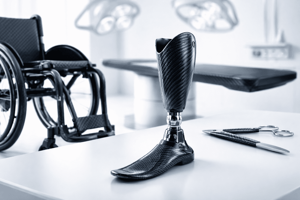
Carbon fiber-reinforced polymer (CFRP) components are prized in motorsport, aerospace, and high-performance automotive applications for their exceptional strength-to-weight ratio. However, even minor manufacturing or service-induced defects—such as voids, wrinkles, and delamination—can drastically compromise structural integrity, safety, and cost-efficiency. For teams, manufacturers, and aftermarket suppliers like JCSPORTLINE, understanding these flaws isn’t just about aesthetics; it’s about performance, liability, and bottom-line economics.
Visual & Structural Impact of the “Big 3” Carbon Fiber Defects
Why These Defects Matter Beyond Looks
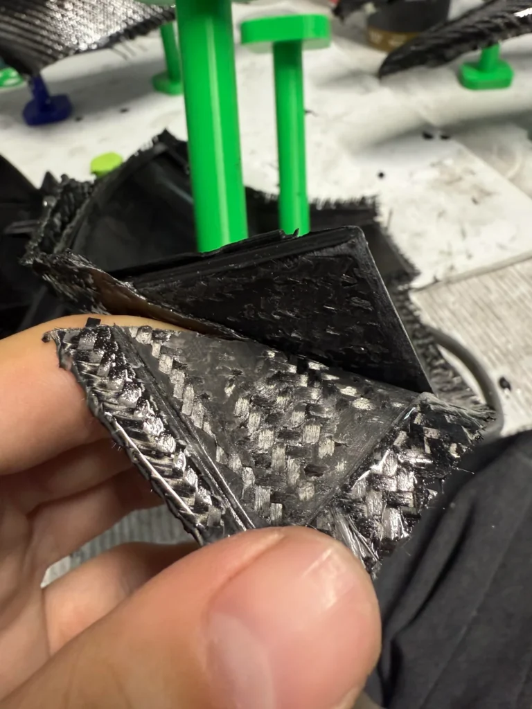
While a glossy carbon weave may look flawless to the untrained eye, subsurface imperfections can silently degrade mechanical performance. Voids (microscopic air pockets), wrinkles (fiber misalignment from improper lay-up), and delamination (separation between plies) are not merely cosmetic—they disrupt load paths critical to part function.
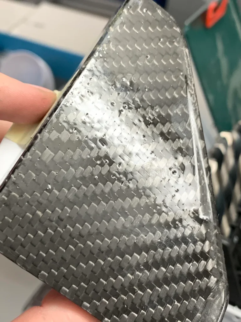
- Voids: Formed during curing due to trapped air or volatiles, voids act as stress concentrators. At >2% volume fraction, they can reduce tensile strength by 5–10%, compressive strength by up to 20%, and interlaminar shear strength (ILSS) by 15–30%.
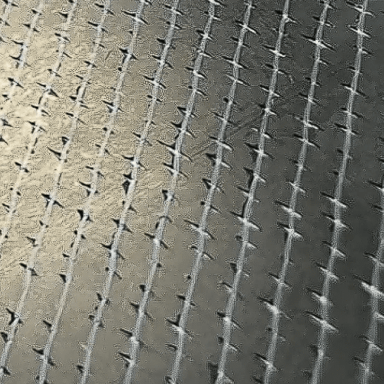
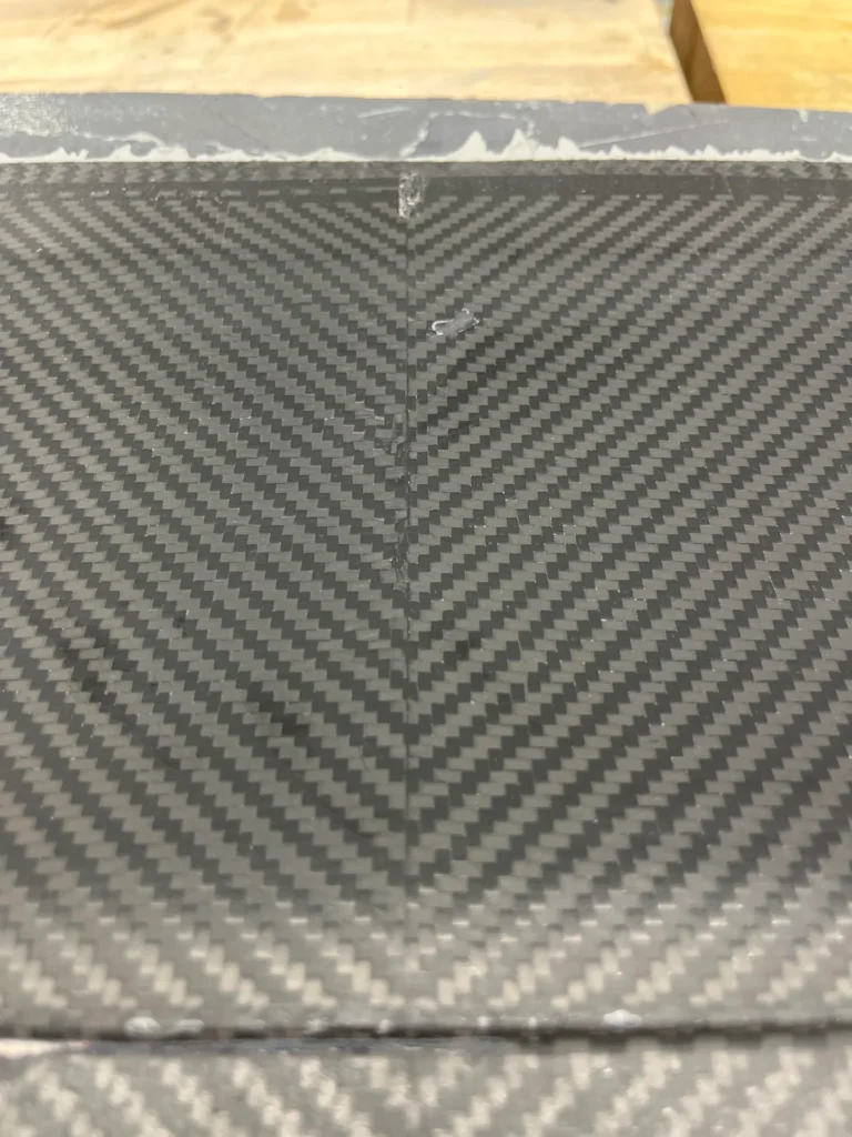
- Wrinkles: Cause localized fiber buckling, leading to premature microcracking under compression. Even small wrinkles in high-stress zones (e.g., suspension mounts) can cut compressive strength by 25% or more.
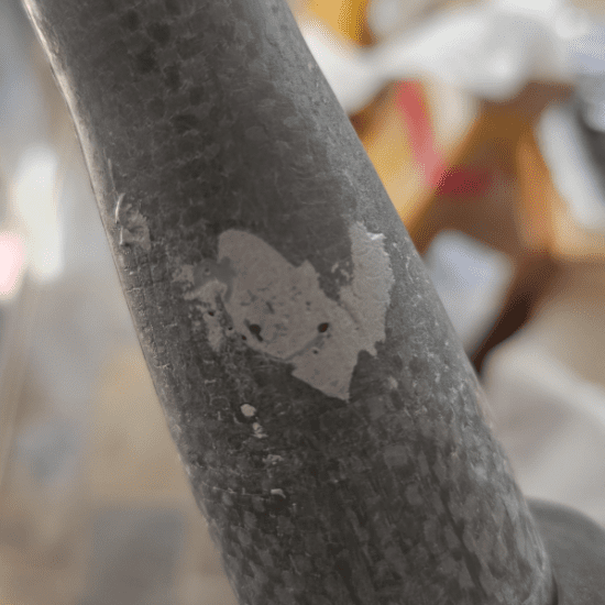
- Delamination: Severely weakens through-thickness load transfer. A delaminated area under torsional load—like a chassis brace or splitter—may lose 40–60% of its effective stiffness.
Warranty & Liability Risks
For aftermarket parts, undetected defects can lead to field failures. A delaminated front splitter detaching at speed isn’t just a repair issue—it’s a safety hazard and legal liability. OEMs and race teams increasingly demand traceable quality records, making defect documentation essential for warranty claims.
Value Proposition: Quantifying defect severity allows informed decisions: repair, rework, or scrap? This prevents costly recalls and preserves brand reputation.
Root-Cause Analysis – Why Voids, Wrinkles & Delamination Happen
Understanding defect origins enables proactive prevention—whether you’re auditing your own shop or evaluating a supplier.
Voids – Moisture, Air Entrapment, Cure Pressure Issues
Voids primarily stem from inadequate consolidation during cure. Key culprits:
- Prepreg moisture >0.2%: Absorbed humidity vaporizes during cure, forming bubbles.
- Insufficient debulking: Skipping intermediate vacuum cycles traps air between plies.
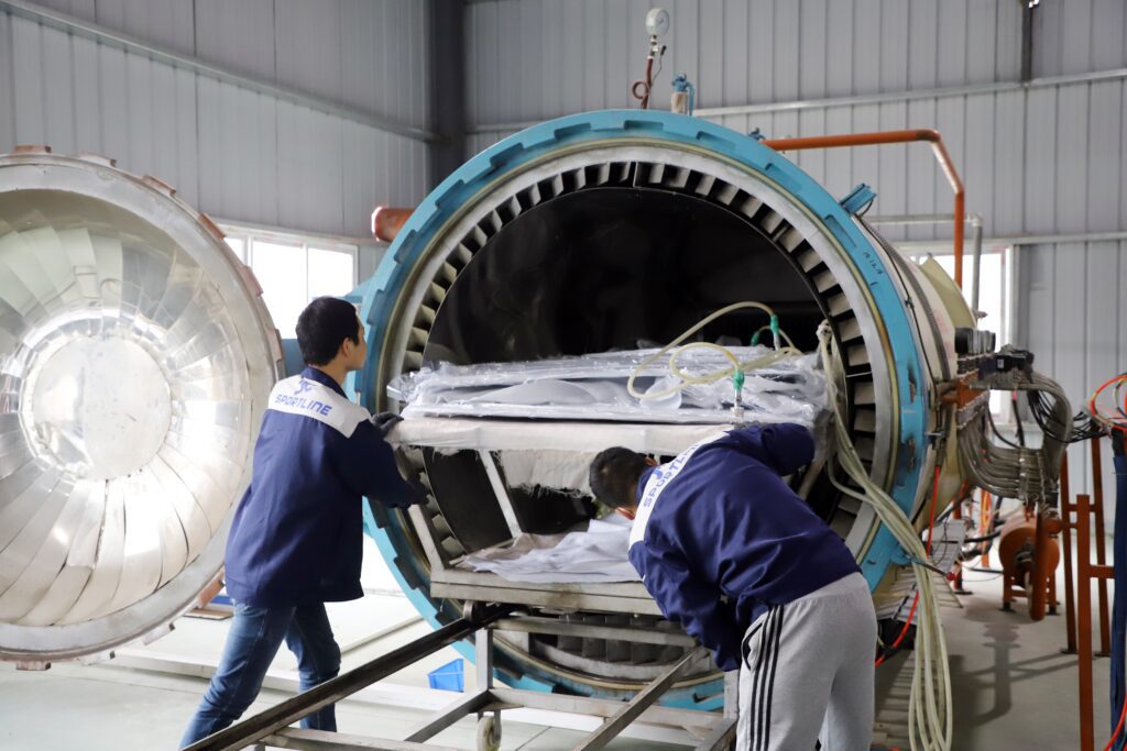
- Low autoclave pressure (<6 bar for epoxy): Fails to compress resin and expel volatiles.
Prevention Tip: Monitor material storage logs and autoclave pressure profiles. Prepreg should be stored at ≤ -18°C with <5% RH, and debulked every 5 plies at -0.85 bar for 10 minutes.

Wrinkles – Lay-Up Tension, Tool Geometry, Bag Bridging
Wrinkles arise when fibers slip or buckle during draping. Contributing factors:
- Excessive or uneven lay-up tension: Causes shear-induced fiber movement.
- Sharp tool radii: Male tools with radii <3x ply thickness induce kinking.
- Poor vacuum bagging: Pleats or bridging create localized compression zones.
Technician Checklist: Use laser projection for precise ply placement, maintain consistent hand tension, and follow pleat protocols to avoid bag-induced wrinkles.
Delamination – Impact, Thermal Cycling, Poor Surface Prep
Delamination often starts invisibly. Common triggers:
- Barely Visible Impact Damage (BVID): Impacts as low as 4 Joules (e.g., dropped tool) can cause internal ply separation.
- CTE mismatch: Combining carbon fiber with metals or different composites induces thermal stresses during cycling.
- Low adhesion energy (<200 J/m²): Inadequate surface prep or contaminated bonding surfaces weaken interlaminar bonds.

QA Action: Implement regular NDI inspections after transport or track use, especially on monocoques or aerodynamic components.
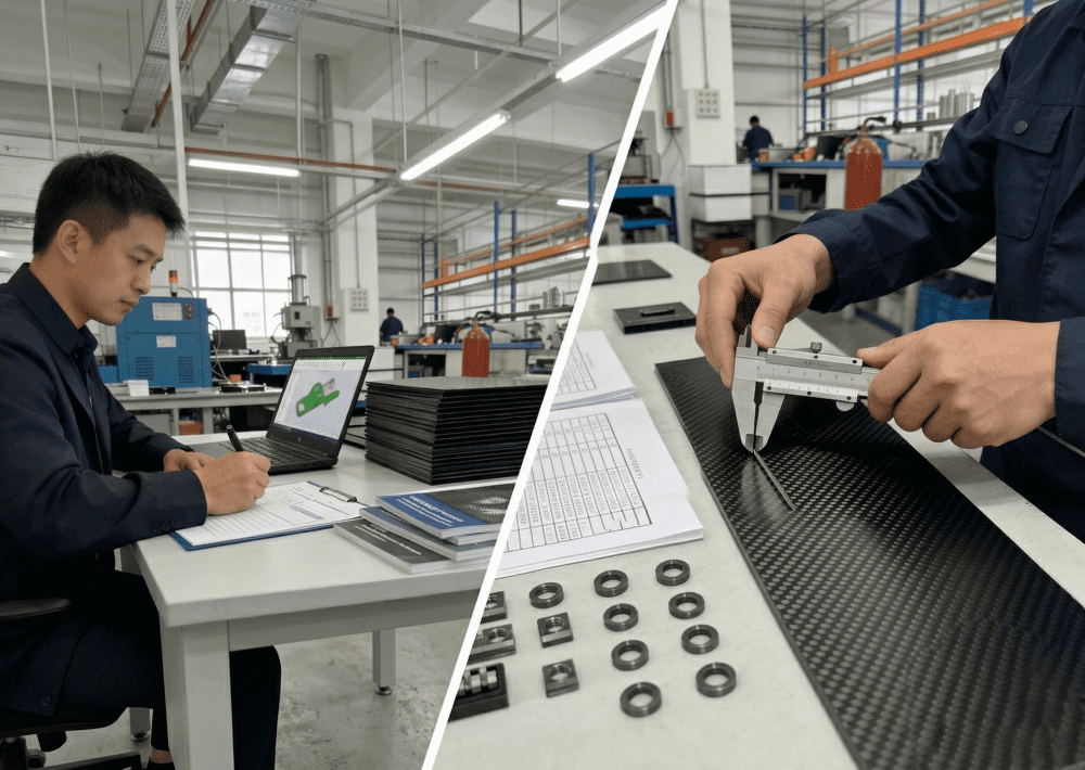
Non-Destructive Inspection & Acceptance Criteria
Detecting defects early saves time and money. Not all inspection methods are equal—budget and precision must align.
Tap Testing, UT C-Scan, Phased Array
| Method | Cost | Resolution | Best For |
|---|---|---|---|
| Tap Testing | Low | Low (surface only) | Quick field checks |
| Ultrasonic C-Scan | Medium-High | High (depth-resolved) | Voids, delamination mapping |
| Phased Array UT | High | Very High | Complex geometries |
- Use ≥2 MHz transducers to distinguish individual 2mm plies.
- Follow ASTM E2580: Void content should stay <2% for structural parts.
For Small Teams: Start with tap testing for gross defects, then invest in portable UT for critical components.
Accept vs. Scrap – Aerospace vs. Automotive Thresholds
Standards vary by industry:
- Aerospace (Airbus AITM 5-0008): Allows Grade 2 porosity (isolated voids ≤1mm, <1.5% area).
- Motorsport: Typically permits <1% wrinkle area in high-stress zones (e.g., wing endplates, diffuser mounts).
Internal Quality Manuals: Cite these benchmarks to eliminate subjective judgment calls.
Step-by-Step Repair & Prevention Protocols
Effective repairs can restore >80% of original strength—often at a fraction of replacement cost.
Void Filling – Resin Injection & Local Autoclave Re-Cure
- Drill 0.5mm vent/inject ports at ±45° to fiber direction to avoid cutting load-bearing tows.
- Inject low-viscosity epoxy (≤200 cP) under vacuum.
- Post-cure at 120°C for 2 hours to restore glass transition temperature (Tg).
Savings: Repairs cost $150–$300 vs. $500+ for a new JCSPORTLINE splitter.
Wrinkle Smoothing – Heat/Compression or Ply Splice
- Minor ripples: Apply 80°C heat blanket + 0.3 MPa pressure for 30 mins.
- Severe wrinkles: Scarf out affected plies at 1:20 taper ratio, re-lay with matching orientation.
Key Benefit: Maintains aerodynamic smoothness without adding weight.
Delamination Patching – Scarfed External Ply & Co-Cured Doubler
- Grind delaminated zone to a 1:30 scarf (aerospace standard).
- Clean and apply FM300K film adhesive (0.2mm) to prevent resin starvation.
- Cure under vacuum at ≥120°C—autoclave preferred, but vacuum-bag-only acceptable if temperature is controlled.
Outcome: Restores torsional rigidity in chassis braces or roll hoops.
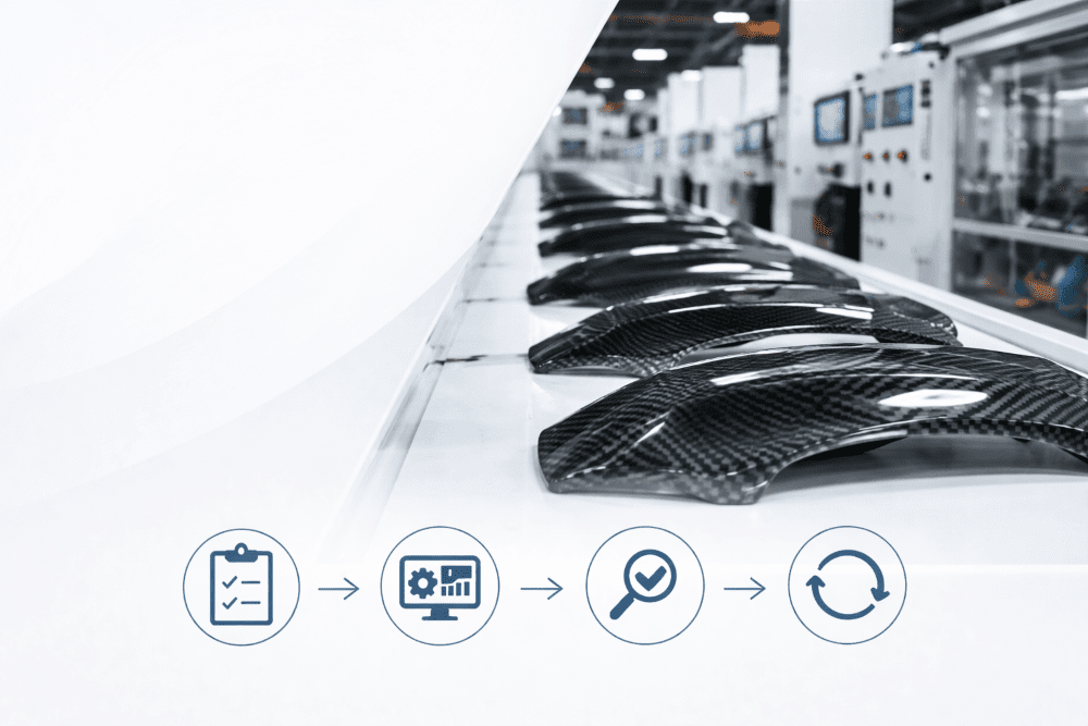
Process Controls to Prevent Recurrence
Systemic fixes drive long-term quality:
- Environmental Control: Store prepreg at ≤ -18°C, <5% RH.
- Debulk Schedule: Every 5 plies, 10 min at -0.85 bar.
- Digital Templating: Use laser projection to eliminate manual handling errors.
Result: Reduces scrap rates from 8% to <2%, directly boosting margins on high-volume JCSPORTLINE parts.
FAQ – Quick Answers to Common Questions
Q: Can I drive with a delaminated splitter?
A: Not recommended. Delamination compromises structural integrity—especially at high speeds. It may detach unexpectedly.
Q: How much strength is lost with 3% voids?
A: Expect 10–15% reduction in ILSS and ~8% in compressive strength—enough to fail under dynamic loads.
Q: DIY resin injection kit or professional shop?
A: For non-structural cosmetic parts, DIY may suffice. For load-bearing components (e.g., hoods, wings), use certified repair services to ensure proper cure and alignment.
Q: Cost to repair a 10 cm wrinkle on a hood?
A: Typically $200–$400, depending on severity and finish requirements—far less than a $1,200 replacement.
Pro Tip: JCSPORTLINE offers certified repair services with strength validation reports—ideal for race teams needing compliance documentation.
By mastering defect identification, root-cause analysis, and validated repair techniques, performance builders can maximize part lifespan, minimize risk, and protect their investment in carbon fiber technology. Whether you’re fabricating or sourcing, knowledge is the strongest reinforcement.