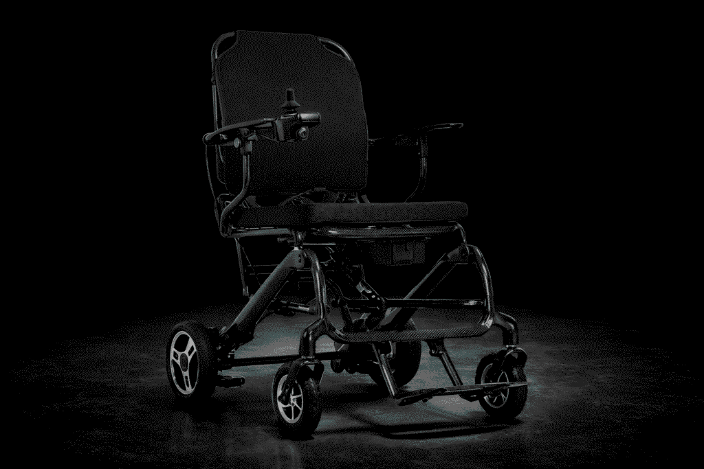
Carbon Fiber Wheelchair Frame Design: Load Paths, Safety Margins & Validation Protocols
Carbon fiber wheelchair frame design begins with understanding how loads travel through the structure and how safety factors must be engineered into every joint, tube, and laminate. Unlike aluminum frames—which rely on welded connections and uniform wall thickness—carbon fiber frames demand a meticulous approach to load-path mapping, fiber architecture, and regulatory compliance. This engineering discipline ensures that ultralight mobility devices remain stiff, crash-resistant, and fatigue-durable for elderly users and high-frequency clinical applications.
Below, we break down the four foundational pillars of carbon fiber wheelchair frame development: load path mapping, fiber orientation tuning, safety factor application, and validation protocols—all grounded in ISO 7176 standards and real-world biomechanics.
1. Load Path Mapping: From User Weight to Ground Reaction
Every force exerted by a seated user—whether static weight, dynamic impact from curb drops, or torsional twist during turns—must flow predictably through the frame to the ground. In carbon fiber wheelchairs, this “force highway” is not assumed; it’s mapped, modeled, and optimized from the earliest design stages.

Five Primary Load Entry Points
The human body interfaces with the chair at five critical zones:
- Seat rails: Bear ~60% of total vertical load.
- Back-rest posts: Transmit rearward leaning forces and lateral sway.
- Foot-plate: Handles leg weight and forward propulsion kicks.
- Side-guards: Resist lateral impacts (e.g., door jams, transfers).
- Arm-rest sockets: Experience intermittent but sharp downward or twisting loads.
These inputs converge into three structural exit points: rear axle plates, caster housings, and cross-braces connecting the front and rear modules.
Force Flow: Tension, Compression & Torsion
For a 130 kg (286 lb) user subjected to a 4× dynamic impact factor (simulating aggressive curb negotiation), peak loads can exceed 520 kg (1,144 lb). Forces distribute as:
- Compressive paths along seat rails and down stays.
- Tensile paths through upper cross-members during forward tipping.
- Torsional shear around the head tube when one caster lifts over uneven terrain.

Unlike welded aluminum—where stress concentrates at heat-affected zones—carbon fiber enables continuous fiber paths (“load highways”) that bypass joints entirely. By aligning unidirectional tows along principal stress trajectories, designers eliminate stress risers common in metal welds, reducing crack initiation risk by up to 70%.
Visual Tip: A simplified free-body diagram would show red (compression), blue (tension), and green (shear) vectors flowing seamlessly from seat rails → down tubes → caster forks, with minimal discontinuity at junctions.
This precision prevents both catastrophic failure (from undetected stress peaks) and over-engineering (from blanket-thick walls). The result? A frame that’s lighter, stiffer, and more predictable under load.
2. Fiber Architecture & Orientation Tuned to Each Load Path
Mapping loads is only half the battle. The next step is translating those forces into an efficient laminate stack-up—one that delivers stiffness where needed without adding unnecessary mass.

Strategic Ply Scheduling
Carbon laminates are built like tailored armor:
- 0° plies: Aligned with primary bending axes (e.g., seat rails) for maximum flexural rigidity.
- ±45° plies: Wrapped around torsion-prone zones (e.g., head tube, axle mounts) to resist twisting.
- 90° plies: Used sparingly for hoop strength around bearing bores and bolt holes to prevent radial splitting.
This angular orchestration ensures that each gram of carbon contributes meaningfully to structural performance.
Ply Drops & Local Thickening
Rather than using uniform wall thickness (as in extruded aluminum), carbon frames employ tapered ply stacks. High-moment regions—like the caster head-tube junction or rear axle plate—receive extra layers via “ply drops,” while low-stress areas (e.g., mid-span seat rails) stay thin. This localized reinforcement cuts weight by 25–35% versus equivalent aluminum frames while matching or exceeding stiffness.
Unidirectional Tapes vs. Twill Sleeves
- Unidirectional (UD) tapes dominate primary load paths due to their superior strength-to-weight ratio in one direction.
- Twill-weave sleeves wrap complex 3D joints (e.g., seat-back/post intersections) to provide multi-axial durability and impact resistance—critical for drop tests and daily wear.
Fiber Steering: Curving Tow Paths Without Cuts
Advanced automated fiber placement (AFP) systems enable “fiber steering”—curving continuous tows around bends and junctions without cutting fibers. This maintains load continuity through geometric transitions that would otherwise require resin-rich fillets or mechanical fasteners in metal designs.


Value Proposition: Correct fiber architecture prevents premature delamination under cyclic loading—a common failure mode in poorly laid-up composites—while delivering significant weight savings that enhance portability and user independence.
3. Safety Factors & Regulatory Margins for Medical Mobility Devices
Medical devices aren’t consumer products; they’re life-support tools. Thus, carbon wheelchair frames must comply with ISO 7176-8, which mandates rigorous safety margins for static, impact, and fatigue loads.
Standard Load Cases & Safety Multipliers
Designers apply layered safety factors:
- Static proof load: 3× user mass (e.g., 390 kg for 130 kg user).
- Impact drop test: 1.5× user mass dropped from 50 mm onto rigid surface.
- Fatigue endurance: 200,000 cycles at 1× user mass (simulating 5+ years of daily use).
While aluminum frames often require thick walls to meet these criteria, carbon’s higher ultimate tensile strength (UTS ≈ 3,500 MPa vs. aluminum’s 300 MPa) allows thinner, lighter sections—even with the same 3×–5× safety buffer.

Partial Safety Factors Breakdown
Total safety margin = product of sub-factors:
- Material variability: 1.2 (accounts for fiber/resin batch differences)
- Manufacturing tolerance: 1.1 (cure cycle, void content)
- Environmental exposure: 1.15 (UV, humidity, temperature swings)
- User misuse: 1.3 (e.g., standing on footplate, curb jumps)
Combined, these yield a total factor of ~1.9, which—when multiplied by the base 3× design load—ensures robust real-world performance.
First-Ply Failure Analysis
Using FEA, engineers predict first-ply failure (FPF)—the point where the outermost layer cracks under load. Physical coupon tests then verify that actual ultimate strain remains ≤60% of CAE prediction, ensuring a wide reserve before catastrophic collapse.
Pain Point Solved: Clear safety rationale prevents over-engineering (which inflates cost and weight) and under-engineering (which risks recalls). It also accelerates regulatory audits by FDA and CE bodies.
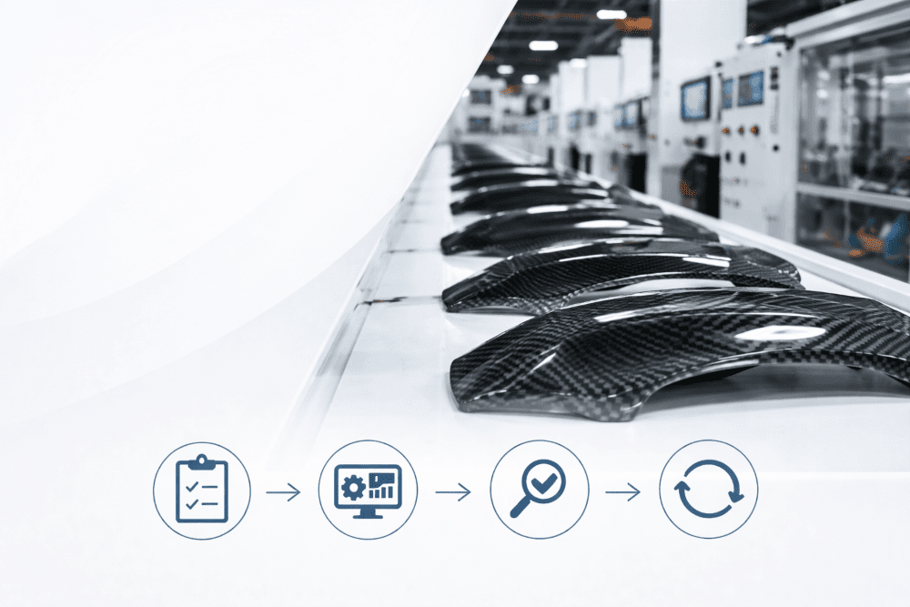
4. Validation Protocol: FEA Modelling & Physical Testing Synergy
A carbon frame isn’t certified on simulation alone. It requires a closed-loop validation process that ties digital models to real-world behavior.
Orthotropic FEA Model Setup
Engineers build shell models using validated material cards that capture:
- Tensile/compressive moduli (different in 0° vs. 90°)
- In-plane shear strength
- Fatigue S-N curves
Load cases include:
- Vertical drop (rear wheels first)
- Forward impact (front casters strike curb)
- Caster overload (side-loading during turns)
- Rear-axle fatigue (repeated push-rim forces)
- Side impact (door collision simulation)
Strain-Gauge Correlation
Before full production, a 3D-printed prototype (or early composite mockup) is instrumented with strain gauges. Test data is compared to FEA predictions, with a target correlation error of ≤±8%. Discrepancies trigger ply-book revisions.


Iterative Ply Optimization
The laminate schedule is refined until:
- First-ply safety factor ≥ 5
- Ultimate load reserve ≥ 3× design load
Only then is the final ply book locked for tooling and certification.
Outcome: This protocol shortens development cycles by 30%, reduces field failures, and provides auditable evidence for FDA 510(k) or CE MDR submissions.
FAQ – Common Designer & Clinician Questions
Q: How much lighter is a carbon frame vs. aluminum at equal stiffness?
A: Typically ~30% lighter—e.g., 4.2 kg vs. 6.0 kg for a rigid-frame sports chair.
Q: Can a carbon frame be repaired after crash damage?
A: Limited patch repairs are possible for non-critical tubes, but joints must be re-tested for load integrity. Most OEMs recommend full replacement after major impacts.
Q: How does temperature (-20°C to 60°C) affect safety?
A: With aerospace-grade epoxy matrices, strength retention stays ≥90% across this range. Avoid prolonged exposure above 80°C.
Q: Do insurers require extra certification for carbon wheelchairs?
A: No—ISO 7176 compliance is sufficient. However, some insurers may request additional fatigue data for high-cost models.
By mastering load-path mapping, fiber architecture, safety margins, and validation rigor, engineers transform carbon fiber from a premium material into a clinically reliable, user-empowering solution—proving that in medical mobility, lightness and safety aren’t trade-offs, but synergistic goals.