
Here is a scenario that happens more often than the industry admits.
A product developer or brand owner has a finished 3D model, a supplier who confirmed they can manufacture it, and a signed tooling purchase order. Three months later, the first samples come out of the mold with material starvation at the mounting points, dimensional gaps that exceed the 1 mm closure tolerance by a factor of three, and a surface finish that bears no resemblance to the Class A specification in the brief. The mold is scrapped. The project restarts. Six months and a significant portion of the development budget are gone.
The part design was not wrong. The supplier was not incompetent. The failure was structural: nobody had run a feasibility study for carbon fiber composite parts before the tooling decision was made. Nobody had asked the questions that a 3D model cannot answer — whether the geometry can be laid up without bridging, whether the mold structure can hold the dimensional tolerance across a production run, whether the bonding method will survive the service loads. Those questions have answers. The answers just have to be sought before tooling begins, not after.
Why do carbon fiber composite parts need a feasibility study when other materials do not require the same rigor? Because the properties of a carbon fiber composite part are not fixed at the material level — they are constructed, layer by layer, decision by decision, from fiber orientation to cure temperature to assembly sequence. A steel stamping is defined by its die geometry and material grade. A carbon fiber part is defined by twenty interdependent variables, every one of which can be specified correctly or incorrectly before production starts.
This is the principle that drives how JCSportline approaches every carbon fiber product development program: a well-engineered carbon fiber part has already been manufactured once — on paper, inside a rigorous feasibility assessment — before a single mold is cut. What the client receives from that process is not a document. It is production certainty, purchased at the only point in the project timeline where it is still affordable.
This article covers what a carbon fiber feasibility study actually contains, why each module corresponds to a specific and quantifiable manufacturing risk, and how to use that framework to determine whether the supplier you are evaluating has genuinely done this work — or handed you a quotation dressed up as engineering.
What Is a Feasibility Study in Carbon Fiber Composite Manufacturing?
A carbon fiber feasibility study is a systematic technical review conducted before tooling is committed. It examines every dimension of manufacturability that the design file cannot reveal on its own: whether the geometry can be formed without defects, whether the mold architecture can hold production tolerances, whether the cure cycle will produce acceptable void fractions, whether the assembly method is structurally adequate.
What is a feasibility study in the general manufacturing sense? A structured pre-production analysis that determines whether a design can be reliably produced at the required quality level and volume. What is a feasibility study in carbon fiber composite manufacturing, specifically? That general definition, applied to a material system where the answer to “can this be made?” depends on a chain of interacting process variables that injection molding and metal forming do not have.
In injection molding, the machine enforces the outcome. Fill pressure, cooling rate, and ejection are controlled by the tool design and machine parameters. The process window is relatively wide and forgiving. In carbon fiber manufacturing feasibility, there is no equivalent of the injection machine. The outcome is determined by the ply-by-ply decisions of the lay-up technician, the thermal uniformity of the cure oven or press, the surface preparation before bonding, the sequence of assembly operations. These variables can be precisely controlled — but only if they are specified before production begins, in a document that the production team is accountable to.
The difference between a supplier who runs a genuine composite feasibility analysis and one who does not is behavioral, not just procedural. A supplier without a feasibility process takes the drawing, calculates a price, and opens a mold. A supplier with one produces a written technical assessment — covering material selection, layup design, mold architecture, process parameters, assembly method, inspection protocol, and testing boundary conditions — before any tooling commitment is made.
For R&D engineers and composite specialists evaluating suppliers, that document is the most reliable signal of actual manufacturing competence available before committing a tooling budget. For sourcing managers and procurement officers, it is the technical basis on which cost risk can be assessed. For automotive professionals and OEM program managers running programs with defined quality and schedule requirements, it is the front-end investment that determines whether the back end of the program will hold.
A feasibility study is not a formality. It is the document that determines whether your carbon fiber project can be manufactured at all — before a single mold is cut.
What Does a Carbon Fiber Feasibility Study Actually Cover?
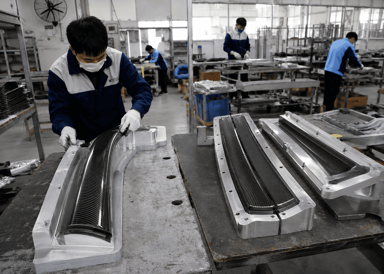
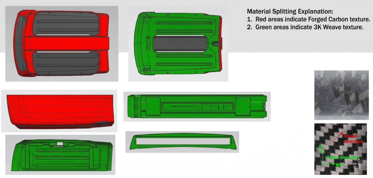
What is included in a carbon fiber feasibility analysis report at JCSportline is drawn from a specific structure — not a template assembled for marketing purposes, but the actual evaluation framework used in a completed feasibility assessment for a full carbon fiber roof assembly system, delivered January 2024. The project required forged carbon matte finish on the exterior top surface, gloss black spray on the side, front, and rear surfaces, plain carbon fiber matte on the interior surface, a nominal wall thickness of 2 mm, Automotive Class A surface quality throughout, and a door-to-body closure gap not exceeding 1 mm in the closed position.
That combination of requirements — large geometry, multi-surface appearance specification, tight dimensional tolerance, structural bonding to metal inserts — represents the kind of program where the gap between a real feasibility process and a notional one becomes visible in the results.
The 14 evaluation modules the assessment covered:
| # | Evaluation Module | Manufacturing Risk Addressed |
| 01 | Customer Product Information | Requirement misalignment before any engineering work begins |
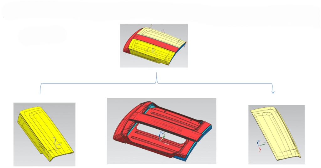
| 02 | Product Structure Proposal | Assembly decomposition logic — outer panel / inner panel / metal inserts — wrong decomposition produces unbuildable sub-assemblies |
| 03 | Primary Material Selection | Fiber architecture and resin system mismatched to structural and appearance requirements |
| 04 | Appearance Definition | Surface quality standard not locked before tooling — Class A expectation discovered after first article |
| 05 | Layup Design | Ply sequence or orientation errors — structural failure or visible surface defect in production |
| 06 | Process Planning | Geometry-process conflicts: undercuts, draft angle inadequacy, bridging-risk zones |
| 07 | Mold and Fixture List | Mold architecture incapable of holding production tolerances across run life |
| 08 | Molding Process Plan | Cure cycle undefined — porosity and dimensional instability batch-to-batch |
| 09 | Machining Plan | CNC reference face obstructed by part geometry — precision machining impossible |
| 10 | Assembly Plan | Bonding method undefined — structural failure at joints under service load |
| 11 | Inspection Plan and Fixtures | No measurable acceptance criteria — quality undefinable and unauditable |
| 12 | Testing Plan | Performance boundary conditions undefined — production parts not validated against service environment |
| 13 | Packaging Plan | Transit damage to finished parts — delivery yield loss on high-value assemblies |
| 14 | Other Requirements | Project-specific requirements outside standard categories |
Three modules are where the difference between serious composite manufacturers and the rest is most clearly visible.
Module 05 — Layup Design is where structural performance and surface quality are either designed in or left to chance. Composite part layup design is not a fiber grade selection — it is a precise specification of which fiber orientation occupies which layer, how transitions between orientations are managed at geometric boundaries, and how the surface layer interacts with the mold surface to produce the required finish. A supplier who cannot produce a ply-by-ply layup schedule before tooling has not done this work.
Module 07 — Mold and Fixture List is where dimensional control is either engineered into the tooling or hoped for in production. The inspection fixture that verifies production part accuracy needs to be designed concurrently with the mold — not commissioned after the first article reveals the mold is producing out-of-tolerance parts.
Module 11 — Inspection Plan is where carbon fiber quality control moves from subjective to systematic. Without defined acceptance criteria and purpose-built inspection tooling, quality is whatever the shift supervisor decides to accept. With a defined plan, it is measurable, repeatable, and auditable — the minimum requirement for any carbon fiber product development program with volume production intent.
The feasibility study for carbon fiber composite product development is, at its most useful, the technical document a client uses to audit a supplier’s real engineering capability before tooling money is spent. Ask for it. If the supplier cannot produce it, that is the answer to the most important question about your project.
Material Selection and Layup Design: Where Production Consistency Is Actually Decided
Carbon fiber material selection is frequently treated as a purchasing decision — which fiber grade, which resin system, which surface weave. In a rigorous composite feasibility analysis, it is an engineering decision with structural and process consequences that propagate through every subsequent module. The selection is not made from a catalog. It is derived from the load cases the part must survive, the surface quality the application requires, and the manufacturing process that can achieve both at the required production volume.
The following layup specification is from a real JCSportline feasibility assessment for a carbon fiber front roof cross-beam — a structural component replacing a two-piece steel assembly consisting of a RP153-780BQ front beam (0.75 mm, tensile strength 1,072 MPa) and a RP153-590BQ reinforcement plate (0.8 mm). The composite replacement was manufactured via HP-RTM using T300 carbon fiber unidirectional fabric and carbon twill fabric laminated with epoxy resin.
| Ply | Material | Fiber Angle | Single Ply Thickness |
| P001 | Twill weave fabric | 45° | 0.25 mm |
| P002 | Unidirectional fabric | 0° | 0.75 mm |
| P003 | Unidirectional fabric | 0° | 0.75 mm |
| P004 | Unidirectional fabric | 0° | 0.75 mm |
| P005 | Unidirectional fabric | 0° | 0.75 mm |
| P006 | Twill weave fabric | 45° | 0.25 mm |
Total laminate thickness: 3.5 mm. Finite element model total mass: 0.718 kg, compared to the original steel assembly at 1.55 kg — a 54% weight reduction that was quantified before the mold was opened, because the material properties and layup were defined precisely enough to model under five load cases: free modal analysis, constrained modal analysis, axial tensile stiffness (5,000 N applied load), bending stiffness, and bending strength.
The material property values used in the finite element analysis were not generic composite properties — they were the specific characterized values for the selected fiber systems:
| Property | UD Fabric | Twill Fabric |
| Density | 1.50 g/cm³ | 1.56 g/cm³ |
| 0° Tensile Strength (Xt) | 861 MPa | 755 MPa |
| 0° Tensile Modulus (E1t) | 90.1 GPa | 63.0 GPa |
| Major Poisson’s Ratio (v12) | 0.316 | 0.023 |
| 90° Tensile Strength (Yt) | 10.5 MPa | 755 MPa |
| In-plane Shear Strength (S) | 27 MPa | 120 MPa |
| Interlaminar Shear Strength | 70.3 MPa | 35.0 MPa |
The ply angle logic is not arbitrary. The 45° twill plies at P001 and P006 manage in-plane shear loads and provide a consistent surface texture. The four 0° unidirectional plies carry the primary axial tensile and bending loads along the beam. This is what composite part layup design means when it is done as engineering rather than approximation: every ply has a reason, and the reason is traceable to a load case.
For mechanical engineers and structural engineers working on appearance-critical components — a 2 mm outer panel in dry carbon manufacturing process — the layup logic operates at smaller scale with the same rigor. 12K fiber in the structural interior layers provides bulk stiffness. 3K fiber in the transition layers smooths the surface before the finish ply is applied. A forged carbon or satin weave surface ply delivers the specified texture and gloss level. The difference between a panel that meets surface waviness requirements and one that shows ply print-through or micro-porosity is determined by the layup schedule — not corrected by post-process polishing.
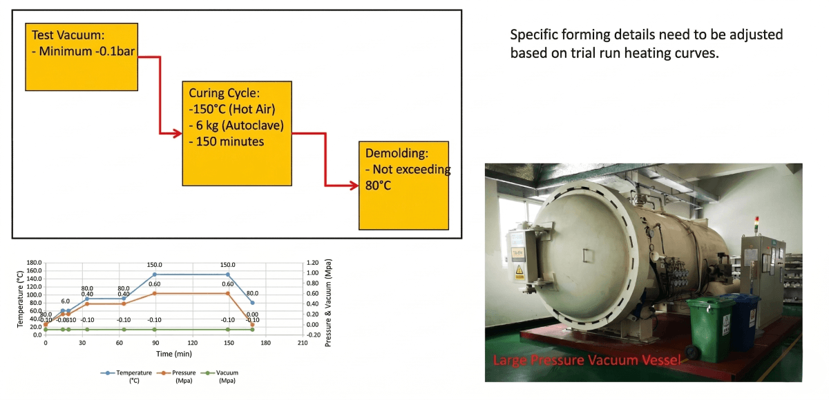
Cure cycle parameters are documented with the same specificity. The process work instruction for a hot-press cure cycle — 150°C process temperature, 6 kg/cm² consolidation pressure, 150-minute cure hold — is not an estimate. It is a validated parameter set derived from process development work, documented so that every production batch runs the same cycle and produces the same void fraction. That parameter set is part of what a genuine carbon fiber manufacturing feasibility review outputs. It is also one of the most direct ways to distinguish a supplier who has done process validation from one who is planning to calibrate against your first production run.
When a supplier provides a laminate schedule with ply orientations, per-ply thickness, and a validated cure cycle in writing before tooling begins, they have already built your part on paper. The alternative is discovering the process variables during your production run, at your cost.
Tooling, Process, Assembly, and Quality Control: The Four Gates No Design Can Skip
Sourcing managers, procurement officers, and brand owners evaluating carbon fiber suppliers regularly encounter the same structural problem: the supplier’s capability presentation describes what they have done on other projects, but gives no reliable signal of what they will do on yours. The four areas below are the evaluation gates where that signal is available — if you ask for the right evidence.
Gate 1: Tooling — Dimensional Control Is Engineered In, Not Adjusted In
Carbon fiber tooling evaluation in a real feasibility context is not primarily about mold material choice or construction method. It is about whether the mold architecture is inherently capable of holding the dimensional tolerances the part requires — not on the first article, but across the full production run.
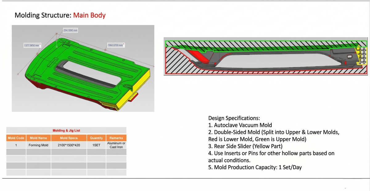
The roof assembly project required a door-to-body closure gap of no more than 1 mm in the closed position. On a large, compound-curve assembly with multiple bonded sub-components, that tolerance cannot be achieved through production-floor adjustment. It is achievable through the right tooling architecture: a dual-face mold structure combined with a rear lateral slide mechanism, both of which were specified in the feasibility assessment before a single mold component was machined. The mold design was the answer to the tolerance requirement — not a production adjustment made after the mold revealed its limitations.
Mold precision is verified against the original 3D data using coordinate measuring machine (CMM) inspection before production parts are run. The inspection fixture used to verify production part accuracy is designed alongside the mold — not commissioned as a reactive measure when the first batch reveals dimensional drift. Carbon fiber mold design review before tooling means the verification method exists before the tool does.
Gate 2: Process Planning — Finding Dead Zones Before They Are Machined In
Every carbon fiber part with machined features has at least one geometry-process conflict waiting to be found. The carbon fiber tooling and process feasibility analysis is where those conflicts are found cheaply.
Reference face obstruction is the most common: a mounting surface that requires precision CNC machining is inaccessible to the cutting tool because another feature in the design — an attachment flange, a stiffening rib — sits directly above the reference plane. The fix at the design stage is a notation on a drawing: reduce the width of the obstructing feature, or add a local relief cut. The same fix after tooling means mold modification, first-article rejection, and schedule impact that compounds with every subsequent step.
Parting line placement produces a different failure: a visible witness line on a Class A surface because the mold split was positioned at a geometry that intersects the appearance zone. The correct position is determined during feasibility — and it requires someone who has seen this failure before to identify it in the model before the tool is built.
Gate 3: Assembly — Bond Line Specification Is a Structural Engineering Decision
For composite assemblies integrating carbon fiber panels with metal inserts or internal structural members, the bonding method is not a detail that production can resolve on the fly. It is a structural specification.
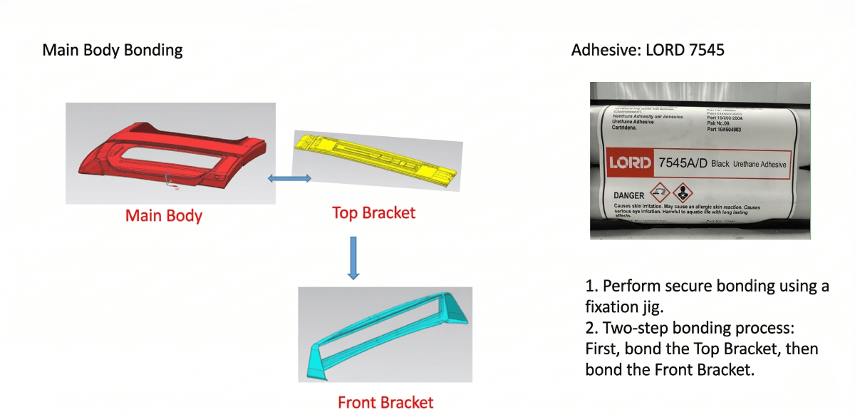
In the roof assembly project, the joining of the carbon fiber inner and outer panels to the metal rail inserts used a step-bonding process with LORD 7545 polyurethane structural adhesive. That adhesive was selected in the feasibility assessment on the basis of bond strength requirements for the joint geometry, surface preparation compatibility with the carbon fiber laminate surface, and environmental resistance under the operating conditions the assembly would see.
Carbon fiber part bonding and assembly feasibility means the adhesive specification, bond line geometry, surface preparation requirements, cure temperature and time, and assembly sequence are all defined before the first part is bonded. When these parameters are left undefined, bond strength variation across production batches is not detectable by dimensional inspection — it becomes visible during service, or during destructive testing, at a point when the cost of correction has grown far beyond what a specification document would have cost.
Gate 4: Quality Control — Inspection Protocol Is Part of the Engineering Package
Carbon fiber quality control at production scale requires purpose-built inspection fixtures matched to the part geometry, acceptance criteria expressed in measurable values, and a test protocol that validates performance against the actual service environment.
The performance validation boundary conditions for a high-pressure intake manifold application — 120°C sustained temperature at 7 bar static pressure, with acceptance criteria of zero leakage and zero structural damage — were defined during feasibility. Those boundary conditions determine what the inspection plan must verify. If they are not defined until after production is running, the production parts may pass every dimensional and visual check and still fail the performance test.
How to evaluate carbon fiber composite manufacturing feasibility at a supplier: ask for the inspection plan and the testing boundary conditions before tooling is committed. A supplier who has done the feasibility work will have written answers.
Why Carbon Fiber Projects Fail Without a Feasibility Study — And What It Actually Costs
Why carbon fiber projects fail without feasibility analysis is consistent across failure modes and across industries. Risk that was identifiable and correctable before tooling was instead discovered during production, when correction costs have compounded. Three patterns recur.
Pattern 1 — The geometry that cannot be manufactured as designed. A steering wheel project presented a mounting point positioned 16 mm from the mold edge. At that clearance, a carbon fiber ply cannot consolidate fully into the feature pocket under press pressure. The result is material starvation, incomplete fiber wet-out, and a structural failure at the mounting point under the first service load. The manufacturable solution — aluminum insert pre-embedding with internal cavity removal to allow bladder forming — was available before tooling. It required a design change and a process specification. Neither was difficult. Both required someone to identify the problem in the model before the mold was built.
Pattern 2 — The dimensional failure that was predictable from the model. A parting line positioned to intersect a Class A surface produced a visible witness mark on every production part. The defect was not detectable from the 3D model without experience-based geometric analysis. It was entirely predictable from a proper carbon fiber tooling and process feasibility analysis — and entirely correctable at the design stage by relocating the parting line to a non-appearance surface.
Pattern 3 — The assembly failure that passed all production inspection. A bonded carbon fiber assembly where the adhesive selection was made by the production team, not specified during engineering. The adhesive was appropriate for the surface preparation method used but inadequate for the bond area and peel load geometry of the joint. Parts passed dimensional inspection. They failed in service.
None of these failures were execution failures. The production teams did what they were asked to do. All three are engineering failures — specifically, failures to convert discoverable risk into documented specification before the tooling decision was made.
How to reduce carbon fiber project risk at the program level is, at its core, a question of timing: identified risks cost less to address the earlier they are found, and a feasibility assessment is the structured mechanism for finding them at the earliest possible point.
The OEM carbon fiber composite product development process that produces reliable results — consistent first-article approval, stable production yields, predictable delivery — has one invariant front end: a complete feasibility assessment, reviewed and signed off before any tooling budget is committed. Programs that invest in this step convert unknown risks into known, specified, manageable ones before the money is spent.
A Feasibility Study Is Not a Cost. It Is the Price of Certainty.
The most expensive decision in a carbon fiber product development program is rarely the material choice or the mold specification. It is the decision to move to tooling without a feasibility assessment — because that decision converts every unexamined design assumption into a budget liability waiting to be triggered.
A complete feasibility study for carbon fiber composite parts produces a specific set of outputs: a ply-by-ply layup schedule with fiber orientations and per-ply thicknesses, a cure cycle parameter set with temperature, pressure, and hold time, a mold architecture recommendation with the dimensional verification method, an assembly procedure with adhesive specification and joint geometry, and an inspection plan with measurable acceptance criteria tied to the actual service environment. These outputs are not estimates or intentions. They are engineering specifications to which production is held accountable.
JCSportline’s feasibility assessments cover all 14 evaluation modules described in this article, applied to the specific geometry, performance requirements, and production volume of each program. The assessments are produced before any tooling recommendation is made — because a tooling recommendation without feasibility data is not engineering advice, it is a guess with a price attached.
For R&D engineers, mechanical engineers, composite specialists, industrial designers, and OEM program managers at the beginning of a carbon fiber program: the 14-module framework in this article is the evaluation standard you can apply to any supplier you are considering. Ask for their feasibility assessment deliverable. Ask which of the 14 modules they cover. Ask for the layup schedule, the cure cycle parameters, and the inspection acceptance criteria in writing, before tooling begins.
Submit your project brief to JCSportline Carbon Engineering Services and receive a structured technical feasibility response within 48 hours.
Frequently Asked Questions
Q1: What is the difference between a carbon fiber feasibility study and a project quotation?
A quotation states price and lead time. A carbon fiber feasibility study states whether the part can be manufactured as designed — and what has to change before reliable production is possible. They answer different questions. A quotation on an unvalidated design is a number attached to an unknown risk profile. At JCSportline, no tooling recommendation is issued without a completed feasibility review, because a quotation is only meaningful if the design has been confirmed as manufacturable at the specified quality level.
Q2: At what stage of a project should I request a feasibility study?
Before the design is frozen — while geometry changes are still drawing edits rather than mold modifications. The minimum viable timing is before tooling is commissioned. The value of a feasibility study for carbon fiber composite parts is directly proportional to how early in the program it is conducted. Programs that begin feasibility work at concept stage consistently reach first-article approval faster and with fewer tooling revision cycles than programs that begin it at the tooling decision.
Q3: What information do I need to provide to start a feasibility assessment?
At minimum: a 3D model in STL or STEP format, the performance requirements (structural loads, operating temperature, dimensional tolerances), the intended application environment, and the target production volume. Physical samples, where available, reduce development time and improve assessment accuracy — particularly for complex assembly geometries where the model does not fully capture the installation interface.
Q4: Can a feasibility study actually reduce tooling cost and development lead time?
The most consistent source of tooling cost overrun in carbon fiber product development is mold modification required after first-article review reveals a manufacturability problem that was present in the design before tooling was committed. A complete composite feasibility analysis finds those problems when they are drawing changes. Programs where feasibility has been thorough reach first-article approval in fewer cycles, with lower total tooling cost, than programs where it was skipped or abbreviated.
Q5: How do I know whether my supplier has genuinely run a feasibility review — or simply provided a quotation?
Ask for the deliverable. A supplier who has conducted a real carbon fiber manufacturing feasibility review will produce a written document — not a verbal summary — covering at minimum: ply-by-ply layup schedule with fiber orientations and thicknesses, cure cycle parameters with temperature, pressure, and hold time, mold structure recommendation with the dimensional verification method, assembly procedure with adhesive specification, and inspection acceptance criteria. If the supplier cannot provide this document before tooling begins, the feasibility work has not been done. The absence of the document is the answer.
Q6: Is a feasibility study necessary for prototype or small-volume carbon fiber programs?
The scope scales with the program, but the core questions do not change. For prototype work, the critical modules are geometric manufacturability, layup design, and mold structure — because these determine whether the prototype can be built at all, and whether it will be representative of what a production part would look like. A prototype built without resolving these questions is not a prototype — it is an expensive sample of an unknown design. A scaled feasibility review for a prototype program costs substantially less than rebuilding a prototype that failed because a fundamental manufacturability issue was not identified before tooling.