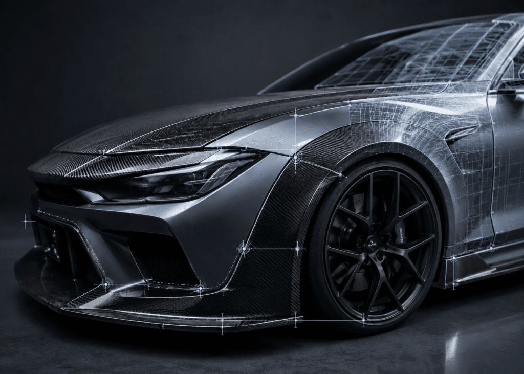
Moving a CAD model or a 3D scan straight into tooling is the fastest way to turn a promising body kit into a pile of parts that need drilling, sanding, and shims before they bolt on. For procurement leads, performance-parts developers, and aftermarket brand owners, carbon fiber parts fitment is rarely lost on the bench. It is lost in the questions never asked before the mold was cut.
Most buyers ask a supplier two things: “What mold do you use?” and “Can you do carbon fiber?” Neither predicts whether a part mounts cleanly on car number one and on car number two hundred. Custom automotive carbon fiber parts fitment is not bought with an expensive mold, and it is not rescued afterward by enlarging holes. It is the output of a closed verification loop that runs from raw data to mass production.
Wrong question: “What mold material do you use?”
Right question: “How do you audit my data, verify the mold, check the first article, control mass production, and prove the mounting position stays consistent over time?”
Why Carbon Fiber Parts “Fit at First, Fail in Mass Production”
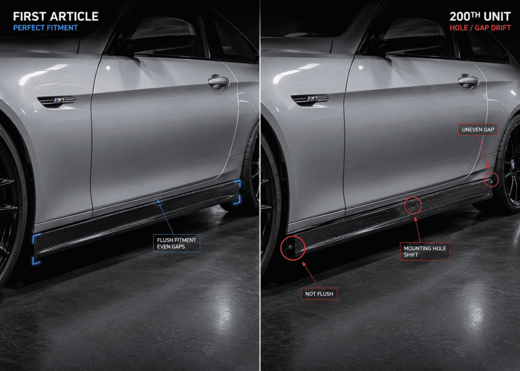
The most expensive fitment problem is not a part that fails on arrival. It is the part that fits perfectly as a first article and then drifts. Why carbon fiber parts fit at first but not in mass production comes down to three mechanisms: molds deform under repeated cycles, trim references drift between operators, and small hole offsets accumulate batch over batch.
The cost lands on the people closest to the buyer. Dealers and installers absorb it — reaming carbon fiber parts mounting hole accuracy back into spec, sanding edges, forcing panels into place — which feeds straight into labor hours, warranty claims, and end-customer returns. On a full kit, one drifted mounting point cascades: it widens carbon fiber body panel gaps, breaks left-to-right symmetry, and disrupts the continuity of adjacent panels.
If a part fits at first but drifts after fifty units, the problem was never the part. It was the absence of process control across mass production.
Carbon Fiber Mold vs Steel Mold: Material Isn’t What Guarantees Fitment
Sourcing managers worry that a lower-cost mold means lower precision or a shorter life. That instinct confuses the tool with the process. The real carbon fiber mold vs steel mold decision is not “which material is more accurate.” It is “which path controls accuracy at your volume and budget.”
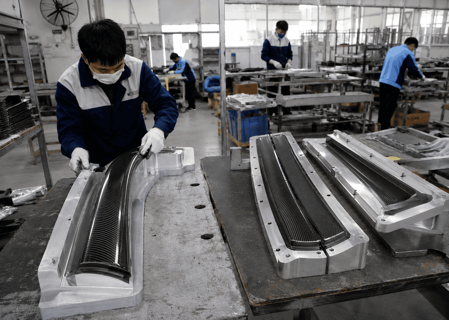
Steel tooling carries a heavy upfront cost that can starve a project of the cash it needs for development and launch. A North American client developing a front lip hit exactly this — steel pricing was high enough to slow their whole R&D and go-to-market schedule. We supplied a carbon fiber mold to bring tooling cost down, and held the installation position to the same target a steel mold would, by comparing 3D data across each production stage so the mounting position stayed consistent even after a large run.
That is the core of carbon fiber mold vs steel mold for fitment accuracy. The carbon mold did not “equal” steel by material physics. It met the project’s requirement because 3D scanning and dimensional inspection verified the geometry at every handoff. That North American result reflects one specific project under its own conditions, not a universal claim.
We do not claim a carbon fiber mold matches steel across every performance metric. We claim that, through staged data comparison and checkpoint inspection, the critical mounting positions meet the project’s requirements.
| Dimension | Steel Mold | Carbon Fiber Mold |
| Upfront cost | High | Lower |
| Lead time | Longer | Faster |
| Fitment-control basis | Staged 3D data comparison | Staged 3D data comparison |
| Best-fit volume | High volume | Low-to-mid volume / cost-sensitive |
The Closed-Loop Verification Chain Behind Real Fitment Accuracy
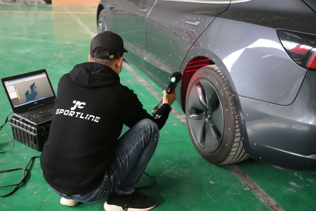
If material does not guarantee fitment, what does? A continuous chain that compares every stage back to one reference — the original 3D data and the OEM mounting points. This is what separates carbon fiber fitment accuracy as an engineering outcome from “it looked fine when we eyeballed it.”
| Stage | What Is Compared | Method | What It Catches |
| 1. Data audit | Client scan vs design intent | Reverse engineering review | Missing surfaces, coordinate offset |
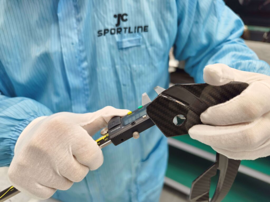
| 2. Mold check | CNC mold vs original 3D | Dimensional inspection | Machining / post-process deviation |
| 3. First article | Part vs data & mold | First-article measurement | Layup, trim, hole position errors |
| 4. Real-vehicle fit | Part on the actual car | Gap & flush inspection | Interference, gaps, symmetry |
| 5. In-production | Mold & part after N sets | Re-comparison | Mold deformation, lifecycle drift |
Data Audit Before Cutting Any Mold
Most fitment failures are imported, not created. A client’s scan can have missing surfaces, coordinate offsets, broken continuity, or an unclear mounting datum. Open a mold from it and you copy the error into every part. Before tooling, we run reverse engineering carbon fiber parts as an audit step: scan completeness, coordinate baseline, surface continuity, installation reference.
A U.S. client came to us with scan data and real fear — earlier projects had shipped with bad installation positions and cost them heavily. Our sequence: audit the data first; after the CNC mold was cut, compare it to the original 3D; after the first part, compare the product to the original data; and after twenty sets, re-compare mold and product to confirm the mold had not deformed. On that project, the path from drawing to sample shortened by two months and project cost came down by 30% — figures that belong to that project under its conditions, not a standing offer. This kind of staged verification leans on dedicated 3D scanning and dimensional inspection rather than an operator’s eye.
First-Article Lock: Turning Sample Standard into Production Standard
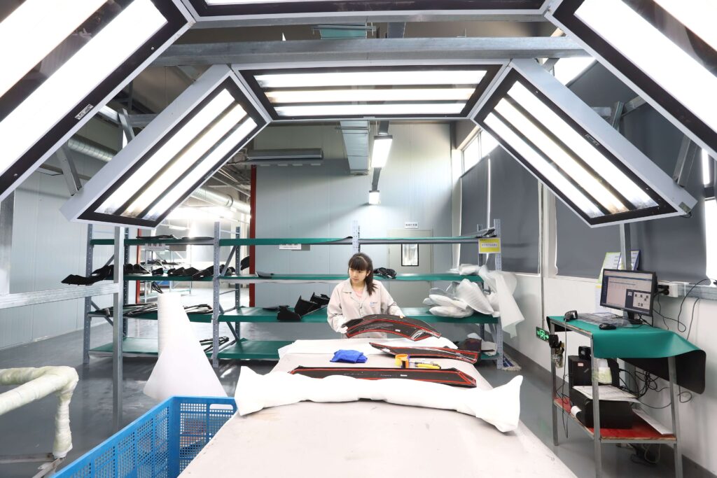
A confirmed sample is worthless if mass production does not inherit it. First article inspection is where we lock the standard — layup direction and stacking sequence, trim boundaries, hole positions, LOGO placement, and the inspection method itself — and then freeze it as an SOP scanned into our MES system so every batch is built to the same first-article baseline.
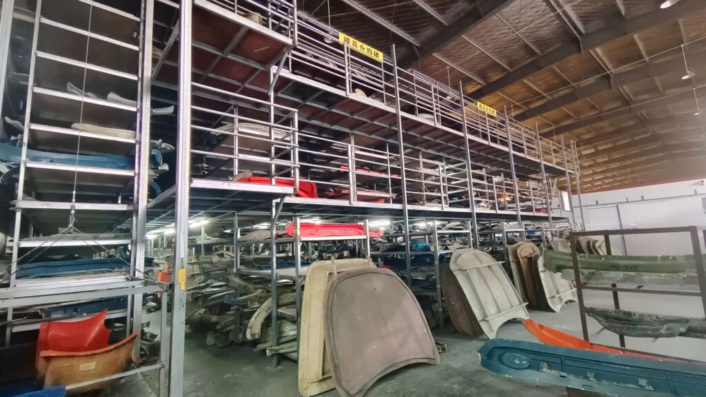
A Taiwanese brand with over a decade in the market had relied on small workshops that could only copy, refused to discuss drawings, and could not scale. We rebuilt the chain: scan → 3D model → confirmed 2D and 3D engineering drawings; standardized layup; a dedicated jig from our inspection fixtures set to fix LOGO up/down/left/right position so every batch matched; unified PPG clearcoat; and 100% inspection of appearance, holes, and alignment. Batch-to-sample consistency rose sharply, and the client began migrating orders over — more than five projects in a year. Their 8–15% weight reduction depended on the structure, layup, and strength of those specific parts, not a fixed figure for every component. This is where carbon fiber body kit panel gap control stops being a hope and becomes a documented target.
Real-Vehicle Check and Mold Lifecycle Monitoring
A trial fit must answer more than “does it bolt on.” Proper gap and flush inspection verifies mounting hole accuracy, fastener accessibility, OEM mounting points compatibility with the original screws, clips, brackets and sensors, symmetry, panel-to-panel continuity, and surface flushness. Mid-production, we re-compare mold and product to catch lifecycle drift before it reaches a customer’s car.
What a real fitment check must verify
- ✔ Hole positions vs original 3D data
- ✔ Original fasteners and brackets still usable
- ✔ No edge interference on install
- ✔ Even gaps across the kit
- ✔ Surface flush with adjacent panels
- ✔ Left-right symmetry
- ✔ Batch-to-batch repeatability
An OEM-mounting-point match is not a marketing claim. It is something we re-measure against the original 3D data at every stage.
Making Small-Batch and Racing Fitment Feasible
Two project types get turned away by most factories: 1–5 set custom runs and tight-deadline race programs. Both still demand precise fitment.
For a small batch custom carbon fiber body kit, the obstacle is development economics — too small for a big-tooling supplier, too precise for a hand-finishing workshop. A Canadian brand building high-end full kits at 1–5 sets per model faced exactly this. We arranged a one-month vehicle rental for real-car data capture and hand-sample development, ran multi-round trial fitting with fast iteration to refine structure, install logic and clearances, then flipped to a mold for repeatable low-volume delivery — documenting key milestones on video the client also used for marketing. The kit met expectations on fit and structure, and within a year they added three more full-vehicle projects.
For race programs, speed cannot mean skipping validation. A UK championship client needed extreme fitment under a hard deadline, so we used 3D printing for carbon fiber prototype fitment to validate structure and mounting position fast. Several prototype rounds failed before we re-adjusted the installation position each time and got it right; the delivery date slipped and was recovered by air freight, and that 60-day timeline belonged to that specific urgent project, not a standard lead time. We describe iteration honestly, because in real engineering, finding and fixing a failed fit is the work.
Aerodynamics, Weave, and Why Install Position Is Part of the Engineering
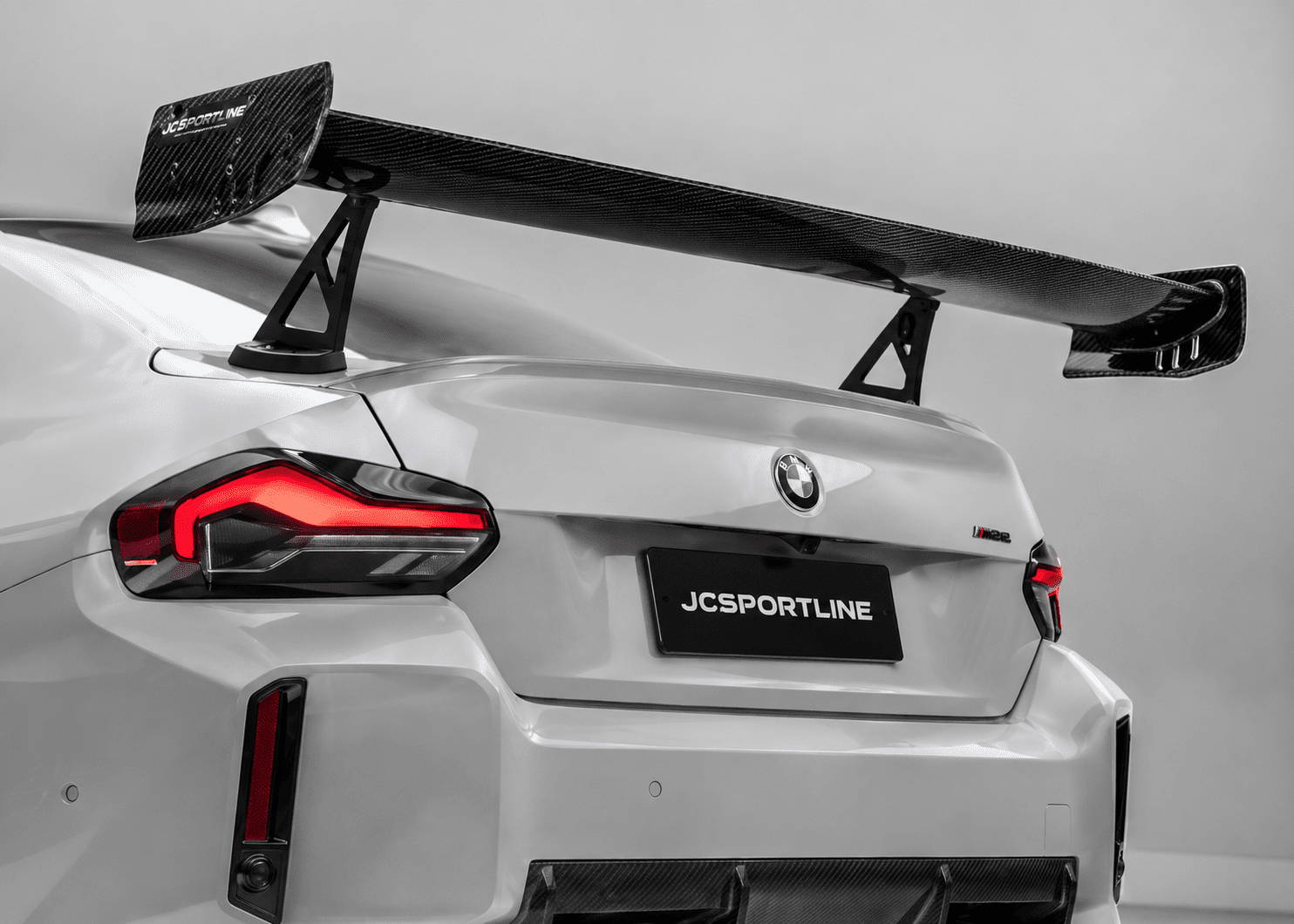
Fitment is not only mechanical. It is aerodynamic. A splitter or wing with sound geometry still loses its designed airflow path if install angle or ride height drift from the design state. Automotive carbon fiber aerodynamics depends on mounting position as much as shape, which is why carbon fiber aerodynamic parts must be validated as installed, not just as drawn.
CFD analysis for automotive parts earns its keep for comparing designs and reading airflow trends — pressure distribution, downforce balance, efficiency. But CFD analysis for carbon fiber car parts is not a guarantee of real-world gains; results depend on boundary conditions, the actual installed state, and validation. We offer it as part of our value-added services and treat it as an engineering comparison tool, not a finished promise.
Appearance carries the same discipline. carbon fiber weave alignment and carbon fiber weave consistency are easy to nail on one sample and lose across a batch; carbon fiber weave alignment between body panels needs a defined centerline standard so a multi-piece kit reads as one design. We will not change a structural layup direction purely for weave aesthetics, nor over-sand clearcoat to chase matte or weight at the cost of the carbon’s original weave and integrity — a line we held on those UK race parts.
The Real Question to Ask Your Supplier
Choosing a carbon fiber supplier is not about the mold in their shop. It is about whether they can audit your data, verify the mold against it, check the first article, control mass production, and prove the mounting position stays consistent over time. That is the difference between a part that photographs well and a part that installs the same way on every car.
Replace “OEM-style fitment” with questions you can check: do the holes match, do the original fasteners work, do edges clear, are gaps even, is the surface flush, is the batch repeatable.
To start a fitment-controlled project, send us:
Vehicle year and trim/version · original vehicle data (scan/CAD) if available · target parts (front lip, side skirts, diffuser, wing, hood, fenders) · mounting method · estimated quantity · appearance requirements · aerodynamic goals.
Bring us the design. We will engineer the fit, prove it stage by stage, and keep it consistent into mass production.
Frequently Asked Questions
How do you control fitment accuracy for custom automotive carbon fiber parts?
We control fitment through 3D scanning, reverse engineering, CAD data comparison, CNC mold accuracy, bracket and mounting point verification, trial fitting where available, and final product inspection before delivery.
Can you support CFD simulation for aerodynamic carbon fiber parts?
Yes. For performance parts such as rear wings, splitters, diffusers, and aero kits, JCSPORTLINE can provide CFD simulation and aerodynamic validation based on project requirements. This can help evaluate airflow behavior, pressure distribution, downforce balance, and aerodynamic efficiency before prototyping or production. CFD support may be charged separately depending on project complexity and scope.
How do you guarantee product quality?
Quality is controlled through material selection, process SOPs, mold accuracy, production inspection, surface finishing standards, fitment checks, and final QC before shipment. For project-based orders, we can define inspection standards and validation items before production.
Do you inspect every product before shipment?
Yes. Finished products are inspected before shipment, including surface finish, key dimensions, mounting points, packaging condition, and project-specific requirements. For B2B orders, inspection standards can be confirmed before mass production.
What if the installation holes or fitment do not match?
Please provide installation photos, videos, and vehicle details. If the issue is confirmed to be caused by manufacturing or fitment deviation from our side, we will take responsibility according to the agreed after-sales policy.