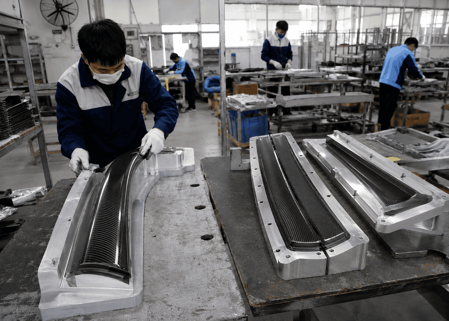
You have something to start with. A body panel someone handmade. A 3D-printed mockup. A competitor’s part you want to improve on. Or just a sketch and a set of rough dimensions. The goal is clear: get it into production as a carbon fiber component that fits correctly, ships reliably, and holds up batch after batch.
What most buyers don’t realize until they’re already six months into the process: the gap between “I have a prototype” and “I have a production-ready carbon fiber project” is not a manufacturing gap. It’s a systems gap. The factories that quote you can make carbon fiber parts. What they typically can’t do — and won’t tell you they can’t do — is manage the data problem, the tooling decision, the process selection, and the fitment consistency across the full development arc. Those capabilities require a different kind of partner.
Carbon fiber prototyping is not a phase. It’s the entry point to a system that runs from data acquisition through tooling strategy, process selection, sample validation, and mass production transfer. Every handoff in that system is a potential failure point. This article identifies where those failure points are, what they cost when they’re missed, and what a sourcing manager, product developer, or OEM program manager should actually be asking before committing to any supplier.
The position here is direct: a supplier who only manufactures is not equipped to run a development program. The buyers who succeed are the ones who find a partner operating with engineering discipline, process flexibility, and local support infrastructure — not just a factory with a low quote.
The Real Reason Carbon Fiber Prototyping Projects Get Stuck
The programs that stall or fail don’t usually fail at the press or the autoclave. They fail at the intake — in the first two weeks, when the wrong assumptions get baked into the tooling decision. Product developers and sourcing managers arriving at this problem for the first time tend to encounter the same three scenarios.
You Have a Prototype But No Production-Ready Data
A buyer has a physical sample — a competitor part, a legacy component, a handmade mockup. The instruction to the factory is “make this in carbon fiber.” The sample goes in a crate, gets shipped to China, clears customs three weeks later (if it clears at all), and arrives with enough dimensional variation from warping and handling that the factory’s reference geometry is already compromised before a single mold design decision has been made.
This is the most common starting point for automotive body kit programs, marine structural components, and consumer electronics enclosures. It’s also the most reliably problematic one. Large parts — aero panels, body kits, yacht structures — are expensive to ship, difficult to protect in transit, and vulnerable to the kind of dimensional distortion that thin-walled fiberglass or foam prototypes accumulate from their own weight. By the time the factory receives the sample, it may have warped 3–5mm at the edges. That deviation doesn’t get corrected during the mold-making process. It gets frozen into the tool geometry.
The secondary problem: even an undistorted physical sample is not precision data. It carries whatever dimensional tolerances were introduced during its own fabrication. Using it directly as a tooling reference transfers those tolerances into every carbon fiber part that mold produces. The carbon fiber fabrication process for structural and exterior components — automotive aero, aerospace panels, medical mobility devices — requires tooling accuracy that a visual-quality physical sample simply cannot deliver on its own.
Local 3D scanning vendors in the US and Europe are set up for reverse engineering workflows. Their deliverables are not the same as the unified-reference, full-surface-coverage data that carbon fiber mold making requires. The gap between what these vendors deliver and what a mold shop needs to cut accurate tooling is real, and the consequences show up as fitment failures after the mold is already cut. Correction at that stage costs multiples of what better data acquisition would have cost at the start.
Tooling accuracy is locked in at the data input stage. That’s the only place it can be controlled.
You Have a Design But No Engineering Path
A product designer or R&D engineer has a surface model — sometimes sophisticated, sometimes a rendered concept with no manufacturing intent behind it. The geometry looks right. What’s missing is the engineering layer that converts design intent into a manufacturable specification. Carbon fiber engineering has requirements that don’t exist in metal or injection-molded plastic design: ply orientation and layup sequence, fiber architecture decisions, resin system selection, mold draft angles designed for repeatable demold, and surface finish requirements that trace back to process selection.
Without carbon fiber DFM — Design for Manufacturability — these decisions get made ad hoc by whoever is running the layup on the day the prototype is built. That works exactly once. It fails the moment a different operator, a different shift, or a higher production volume enters the picture.
The failure mode is consistent: a beautiful first sample that the supplier can’t reproducibly explain. The layup sequence wasn’t documented. The fiber orientation wasn’t verified on-tool. The cure cycle wasn’t controlled to a specification. The sample got approved, production started, and the third batch came back with a surface defect or a fitment deviation that no one can trace back to a root cause — because there was no root cause documentation to begin with.
For OEM program managers running automotive or aerospace development programs, this is not an acceptable risk. For industrial designers and sourcing teams working on consumer electronics or medical devices, where cosmetic consistency and dimensional tolerances are product requirements, it’s equally disqualifying. The DFM review is the step that turns a design file into a manufacturable specification. Skipping it to save two weeks at the start of a project typically costs two months at the end.
You Got Quotes But Can’t Evaluate Them
The third failure mode is the most expensive, because it’s the hardest to diagnose in real time. A buyer issues an RFQ, receives five or six quotes from Chinese carbon fiber suppliers, and observes a price range that spans three to five times on line items that look identical. The instinct is to suspect quality differences. The reality is usually specification differences.
What the buyer can’t see from a price column: one supplier is quoting wet layup, another prepreg. One is quoting a fiberglass splash mold, another an aluminum tool. One has included a DFM review and first-sample validation cycle; another is quoting raw manufacturing with no process documentation.
Carbon fiber rapid prototyping quotes that look competitive at the bottom of the range frequently omit the engineering support, the tooling quality, and the process documentation that make a prototype transferable to production. The buyer who selects the lowest quote discovers this after first sample approval — when the supplier can’t explain how the part was built, or when batch two doesn’t match batch one.
The solution isn’t tighter negotiation. It’s locking down the process specification — fabrication process, tooling material, layup documentation requirements, quality checkpoints — before issuing the RFQ. Our carbon consultant service exists for exactly this: giving buyers with over 90 R&D and engineering professionals behind them an independent technical evaluation before any tooling money moves.
Starting Without a Physical Prototype — How Data Acquisition Changes the Equation
For buyers who don’t have a usable sample — or whose sample fails the dimensional stability test — the development path begins with data. The quality of that data determines the accuracy of every downstream decision.
What Production-Ready Data Actually Means
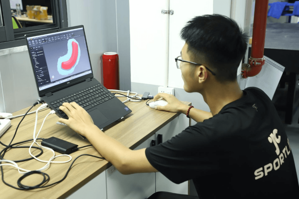
A 3D scan for visualization and a 3D scan suitable for carbon fiber mold making are not the same deliverable. The distinction matters: a visualization scan captures surface appearance. A production-ready scan captures a unified geometric reference system that can be used to generate tooling geometry, verify first sample fitment, and establish a dimensional baseline for production quality control.
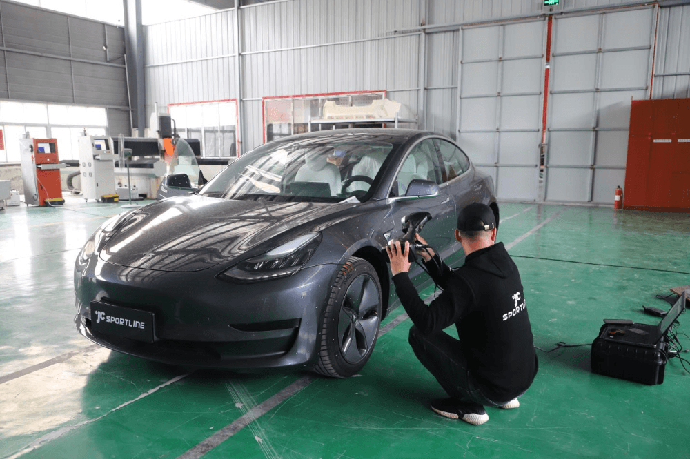
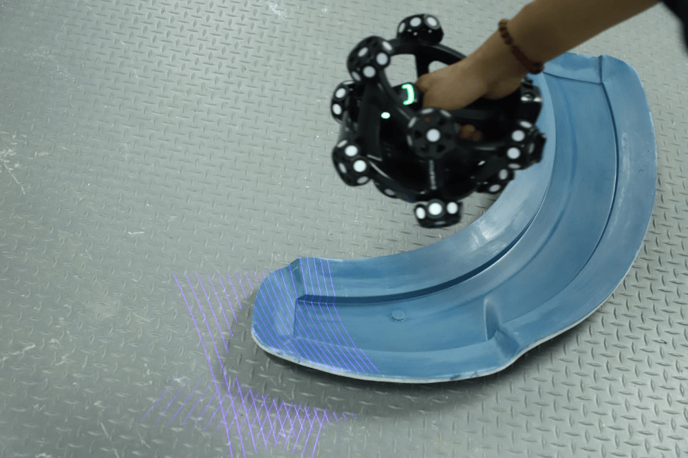
Production-ready data requirements are specific: unified reference coordinate system applied consistently across the entire surface, full coverage with no stitching artifacts or blind spots at mounting interfaces, and dimensional accuracy at the tolerance level that CNC tooling requires. JC Sportline’s dedicated carbon data acquisition team — established in 2023 and expanded globally in 2024 — delivers 0.01mm scanning tolerance with 100% surface coverage, processed and delivered in formats that integrate directly into design and mold manufacturing workflows.
The contrast with conventional scanning is operational, not cosmetic. Fragmented surface capture with manual reference alignment introduces deviation across different zones of the same part. For a body panel spanning 1,200mm, a 0.5mm reference alignment error at one end translates to visible fitment problems when the part meets the vehicle. That deviation is invisible in the scan file. It appears at installation, after the mold is already cut.
For carbon fiber material for prototyping programs where the reference vehicle or part is in the US or Europe, JC Sportline scanning teams travel to the part. This eliminates shipping risk, customs risk, and dimensional degradation that comes from transporting large or flexible reference samples internationally. The 0.01mm tolerance applies whether the scan happens in Shenzhen or at a client facility in Stuttgart or Los Angeles.
When a Physical Sample Can Be Used as the Starting Point for Tooling
Not every program needs a full data acquisition workflow. When a buyer has a sample that meets specific dimensional conditions, it can serve as a direct tooling reference — and the path is faster.
The conditions are: the sample must be rigid enough to hold its geometry under its own weight without measurable deflection, geometrically complete at all mounting and interface surfaces, and representative of the final design intent rather than an early-stage approximation. A fiberglass splash, a foam mockup, or a pre-production soft unit fails the first test. A CNC-machined aluminum reference or a rigid SLA 3D print in accurate-to-final geometry passes.
The valid starting points for a carbon fiber tooling strategy extend beyond physical samples: a qualified dimensional sample, a complete surface model from a design team, a rigid 3D-printed prototype, or a purpose-made reference part in any stable material. Each has different cost and lead time implications. This determination belongs in the carbon fiber prototype development evaluation — an engineering judgment, not a sales call. A supplier who agrees to proceed from a questionable sample without raising this question is making a decision that will cost the buyer later.
Choosing the Right Carbon Fiber Fabrication Process Before You Commit to Tooling
Process selection is the decision with the highest downstream leverage in a carbon fiber development program. It determines unit cost, production scalability, surface quality ceiling, and tooling investment. It also determines which failure modes are available to you in production. Making this decision after the mold is cut — which is when most buyers are forced into it — means accepting whatever process the supplier defaults to.
Wet Carbon Infusion vs Prepreg vs PCM — What Each Process Actually Delivers
There is no universally correct carbon fiber fabrication process. Each process occupies a distinct position in the trade-off between cost, surface quality, structural performance, and production scalability. The table below reflects the practical reality across the four primary carbon fiber fabrication techniques JC Sportline operates:
| Process | Best Application | Surface Quality | Unit Cost | Production Scalability |
| Wet Layup / Vacuum Infusion | Large aero panels, marine structures, low-volume exterior | Medium | Low | Medium |
| Prepreg Hot Press | High-performance structural / Class-A exterior | High | Higher | High |
| PCM (Compression Molding) | High-consistency medium/small functional parts | High | Medium-High | Very High |
| Overlay | Surface carbon on existing substrate | Medium-High | Low-Medium | Medium |
Wet layup and vacuum infusion are the cost-effective choice for large exterior panels and low production volumes. The resin-to-fiber ratio is less precisely controlled than in prepreg, so mechanical properties and surface finish vary more batch to batch. For body kits and aero components that will be painted, where the primary requirement is light weight and acceptable surface quality rather than structural load-bearing, infusion is often the correct answer — not a compromise.
Prepreg hot pressing delivers the highest and most consistent fiber volume fraction. This translates to superior structural performance and Class-A surface repeatability across production runs. For automotive structural trim, aerospace panels, and medical device components where both surface cosmetics and mechanical properties are specified requirements, prepreg is not optional — it’s the only process that reliably delivers both.
PCM — compression molding is the answer when production volume is the governing variable. Matched metal tooling and closed-mold processing produce consistent parts with tight dimensional tolerances at short cycle times. It is the carbon fiber parts manufacturing process that scales most efficiently into high-volume programs. The upfront tooling investment is higher than open-mold processes, but the per-part economics and dimensional consistency at volume justify it for any program beyond a few hundred annual units.
Overlay is a category unto itself — applying carbon fiber surface material to an existing substrate for cosmetic or localized stiffness purposes. It is not a structural process and should not appear in a specification where structural performance is a requirement.
The error most buyers make: defaulting to prepreg because it sounds most serious, without asking whether the application justifies the cost premium. Prepreg on a painted exterior panel that will never see structural load is a cost decision that delivers no functional benefit. Wet infusion on a structural bracket is a specification error that will show up as field failures. Process selection is an engineering decision based on the part’s actual functional requirements — not a preference for the most sophisticated-sounding option.
How Process Selection Affects Tooling Strategy and Total Project Cost
Process and tooling are a linked system. The fabrication process determines mold material requirements, mold construction method, thermal cycle requirements, and mold life expectancy — all of which feed directly into tooling cost, lead time, and the total capital investment the program requires.
Wet layup and infusion can use fiberglass splash molds taken from a physical sample. These are fast to produce, low-cost, and appropriate for rapid iteration in early development. Their thermal cycle stability is limited — surface quality and dimensional accuracy degrade faster than hard tooling, making them unsuitable as permanent production tooling for any program with consistent quality requirements.
Prepreg and PCM require aluminum or carbon fiber composite tooling capable of withstanding the cure temperatures and pressures involved. These molds maintain dimensional accuracy through high production volumes and deliver the surface consistency that Class-A programs require.
A staged carbon fiber tooling strategy is the practical framework for most development programs: soft tooling for the first prototype iteration to validate geometry and fitment at low cost, transitioning to pre-production hard tooling once the design is frozen, then to production tooling once the process is validated and volume is confirmed. Our grinding and tooling capabilities cover this full progression — from rapid soft molds through precision CNC hard tooling.
The implication for carbon fiber machining and procurement: the tooling budget is not a fixed number at program start. It scales with development stage and production intent. Any supplier who quotes a single tooling cost without asking about production volume and development stage is not accounting for the full context.
From First Sample to Mass Production — How Fit Consistency Is Maintained
A good first sample is evidence that the geometry works. It is not evidence that the process is production-ready. This distinction is where most programs encounter their most expensive surprise.
Why Most Prototype-to-Production Gaps Happen
The failure pattern is predictable. First sample passes. Buyer approves. Production begins. Batch three or batch ten arrives with mounting points that are 2mm off — not enough to make the part obviously wrong, but enough that installation requires rework or the part doesn’t clear adjacent body lines consistently.
The causes trace back to the same set of missing controls. The prototype mold was never documented with a verified digital baseline. When it was repaired or replaced, no one had a geometric reference to build back to. The carbon fiber manufacturing machines ran slightly different parameters on the production run — cure temperature, pressure cycle, vacuum level — because those parameters were never locked in a specification document. The layup sequence existed in an operator’s muscle memory, not in a written SOP.
These are not unusual events. They are the default outcome of a carbon fiber prototype to production transition that was managed as a commercial handoff instead of an engineering transfer. The sample gets approved. Production starts. The documentation, the process lock, and the dimensional baseline that would make every subsequent batch traceable back to the approved sample simply don’t exist.
Composite prototypes built without production intent from day one almost always require partial redesign before stable mass production is achievable. For automotive OEM programs and medical device manufacturers, this redesign cycle — recutting tools, re-qualifying the process, re-verifying fitment — is the kind of delay that moves product launch dates by quarters, not weeks.
JC Sportline’s Data-Anchored Production System
Every project at JC Sportline begins from 3D precision data — and that same data is the reference point for every subsequent stage of the program. The scanning geometry that informed the tooling design is the baseline against which first sample fitment is verified, against which each production batch is checked, and against which any tooling repair or replacement is evaluated. The data doesn’t change. The parts have to match it.
The development sequence is defined and documented: Engineering & DFM review before tooling commitment — conducted by engineers, not sales — followed by tooling strategy selection, prototype build with layup sequence documented and cure parameters controlled to specification, fitment and dimensional validation against the 3D baseline using dedicated inspection equipment, and then a controlled handoff to mass production with process parameters locked in SOP and quality checkpoints built into the production flow.
The R&D infrastructure behind this workflow includes over 90 professionals across design, process engineering, project management, and validation testing — supported by PhD-level specialists in polymer chemistry and composite material applications, and senior experts in vehicle dynamics and structural optimization. This is the team that conducts the DFM review, defines the process specification, and owns the quality baseline. Not the sales team.
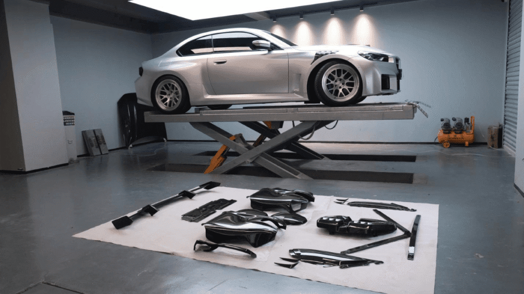
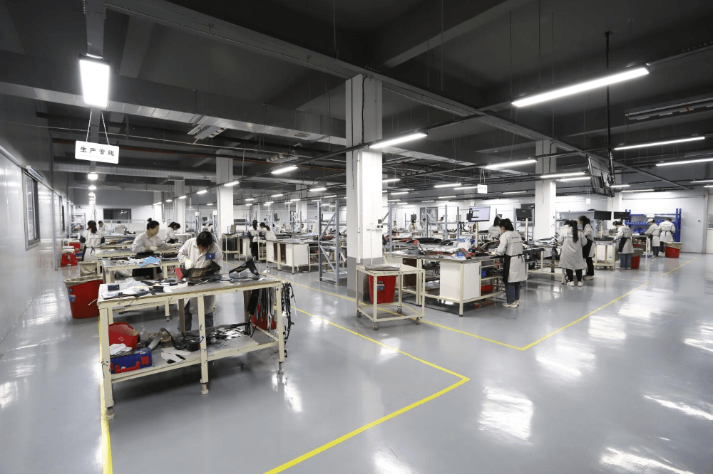
The Nissan 400Z body kit program benchmarks what this system delivers under pressure: drawing to validated mold in 58 days, with PLM-tracked milestones, SOP-controlled quality checkpoints at every stage, and a continuous feedback loop from first sample quality resolution back into production process standardization. Our manufacturing facilities across three production sites in China support this with autoclaves, compression molding equipment, and non-destructive testing infrastructure — ultrasonic testing and X-ray imaging for real-time quality monitoring.
JC Sportline holds ISO 9001 and IATF 16949 certification. These are external audit frameworks that require the process documentation, control point architecture, and issue escalation protocols to be verifiable on demand — not self-declared. For automotive OEM and brand clients, this is the minimum credible quality baseline.
The question to ask any carbon fiber prototype manufacturing supplier: show me the process that connects the approved first sample to batch 50. If the answer is “we keep the mold and use the same operators,” that is not a quality system. It is an assumption that conditions won’t change.
The Local Support Problem — Why a China-Only Factory Can’t Fully Serve an International Development Program
Manufacturing capability is necessary. It is not sufficient. The half of the equation that most buyers don’t price in until they’ve already experienced the problem: what happens after the parts ship.
The bottleneck in most China-sourced carbon fiber projects isn’t manufacturing quality — it’s communication latency and the absence of local accountability.
The mechanics are straightforward. A buyer in the US or Europe receives a production batch with a fitment deviation. They document it with photos and measurements and send it to the sales contact at the Chinese factory. That contact translates the issue — literally and technically — and relays it to the engineering or production team. Best case: two to three days for a substantive response. More commonly: a week, with technical distortion introduced at each translation step, so the specific 1.8mm deviation at the rear mounting bracket becomes “some quality issue” in the internal communication.
For carbon fiber projects in active development — iterative sampling, design changes being incorporated, production timelines being managed — this communication structure is a systematic cost multiplier that extends every iteration cycle and increases the total program cost in ways that never appear on the original quote.
JC Sportline operates with a US-based team (direct line: +1 585 606-0701) and European support presence. Local teams can receive samples, assess fitment issues directly against vehicle or assembly references, and coordinate technical responses with the China engineering team in real time — eliminating the translation-relay overhead. After-sales handling, returns, and replacements run through local logistics. For standard resolution scenarios, no international shipment is required.
This is not a support feature. It is a project execution capability. A composite manufacturer serving international OEM and brand clients while operating exclusively from China cannot provide the response speed and local verification those programs require. Any buyer evaluating a china carbon fiber prototyping manufacturer should treat the presence of a functioning local team — not a forwarding number, but an actual team with technical capability — as a baseline qualification, not a differentiator.
The carbon consultant and brand protection services extend this model further: IP documentation, design ownership tracking, and brand-specific production controls managed through local oversight. The designer resources program provides an additional layer of design documentation and supplier accountability that a standard purchase order relationship doesn’t include.
How to Evaluate a Carbon Fiber Prototyping Manufacturer — A Practical Checklist
Every item in the table below corresponds to a specific failure mode documented in the sections above. None of these are unreasonable requirements. A supplier who can’t answer them is telling you how much of the problem-solving will fall on your side when the program hits its first obstacle — and every program hits one.
| Evaluation Dimension | Questions to Ask | Red Flag Response |
| Data Capability | Can you perform 3D scanning or data acquisition to 0.01mm tolerance? Can you travel to our location? | “Send us the sample and we’ll figure it out” |
| Process Flexibility | What fabrication processes do you operate? How do you recommend a process for a specific application and volume? | One process offered, no recommendation logic |
| Tooling Strategy | What tooling stages do you support? Can you start from a 3D print or a soft prototype? | Direct quote without feasibility evaluation |
| Fit Consistency | How do you verify that production batches match the approved first sample? What inspection equipment? | “We have experience” / visual inspection only |
| Local Support | Do you have a functioning US or EU team — not just a phone number? How is after-sales handled locally? | China contact only, international return required |
| Certifications | Are ISO 9001 and IATF 16949 current? Can you provide documentation on request? | Unable to provide certificates on request |
| Engineering Depth | Who conducts the DFM review — engineers or sales? Can I speak directly with the engineering team? | All technical questions routed through sales |
A supplier who clears all seven dimensions is not guaranteeing a perfect program. But a supplier who deflects or can’t answer four of these seven is showing you the organizational structure that will be managing your tooling investment.
The best composite prototypes come from suppliers who treat the intake evaluation — the first two weeks — as rigorously as the manufacturing itself. A supplier who finds these questions irritating is a supplier who hasn’t built the systems to answer them. Our team page documents the engineering and project management structure behind these capabilities — including the R&D professionals, PhD advisors, and cross-functional specialists who own each stage of the development workflow.
Conclusion
Three factors determine whether a carbon fiber prototyping program reaches stable production — and none of them are about carbon fiber manufacturing skill. The first is data quality: whether the tooling is built from a verified geometric reference or from an assumption. The second is process selection: whether the fabrication method was chosen before tooling commitment based on functional requirements and production intent, or defaulted to after the fact. The third is local accountability: whether there is a team in the buyer’s market that can close the loop on sample review, design iteration, and after-sales resolution without the two-week delay of international relay communication.
A factory with strong manufacturing capability but none of these three operating conditions will produce a good first sample and an unpredictable production program. The buyers who get to stable mass production — automotive OEM managers, product developers in consumer electronics, sourcing directors in marine and medical — are the ones who identified a partner with all three capabilities before signing the first purchase order, not after.
That’s what this article is for. Not to explain carbon fiber. To give you the evaluation framework to find the right partner before the program starts — and to understand what you’re actually buying when you choose based on price alone.
If you’re at any stage of a carbon fiber development program — with a prototype, with data, with a concept, or rebuilding a program that stalled — JC Sportline’s engineering team provides free project feasibility assessments covering materials, process route, tooling strategy, and timeline. The assessment is conducted by engineers with over 20 years of composite manufacturing experience, backed by a 90+ person R&D organization. No commitment is required to find out whether your project can be done correctly.
FAQ
1. My prototype is too large or fragile to ship to China — what are the actual options?
Shipping large or structurally soft prototypes internationally creates dimensional risk and customs complications that have derailed programs by four to six weeks. The alternatives: provide a complete surface model from your design team if it reflects final design intent accurately; use a rigid 3D-printed reference (SLA or SLS) built to final geometry; or engage JC Sportline’s data acquisition team to perform on-site scanning at your location. The team travels globally — the 0.01mm scanning tolerance is the same whether the scan happens in China or at a client facility in the US or Europe. This option is typically faster and cheaper than international sample logistics once customs delays are factored in.
2. What’s the real difference between wet infusion and prepreg for a prototyping project — and why does it matter now rather than later?
It matters at the prototype stage because the process you build the prototype in should be the process you intend to scale. Wet infusion and prepreg produce parts with meaningfully different fiber volume fractions, surface finish consistency, and dimensional tolerances. A prototype built in wet infusion that gets approved, then shifted to prepreg for production, is functionally a new validation cycle — the process change invalidates the sample approval. The right sequence: determine production process first based on performance requirements and volume, then build the prototype in that process. Process selection is an engineering input to the tooling decision. Visit our carbon fiber engineering page for how this evaluation works in practice.
3. Can tooling start from a 3D-printed prototype instead of a physical sample?
Yes — under specific conditions. The 3D print must be built in a dimensionally stable rigid material (SLA, SLS, or similar), must accurately represent final design intent including all mounting interfaces, and must not have open development decisions embedded in its geometry. A 3D print that meets these conditions can be digitized and used as the direct basis for tooling geometry, or used as a pattern for soft mold production. A 3D print that is a conceptual approximation rather than a final-intent model is a visual reference, not a tooling input. Starting tooling from a non-final geometry means the mold gets cut twice.
4. How do you actually guarantee that production batches will fit the same as the approved sample?
The guarantee is structural. Every program starts from a documented 3D precision baseline. That baseline is used to verify the first sample’s installation interfaces using dedicated inspection equipment — not visual assessment. After first sample approval, the layup sequence, cure parameters, and process controls are locked in a written SOP. Production batches are verified against the same 3D reference at defined checkpoints. Tooling is maintained against the original digital geometry. When the baseline, the SOP, and the inspection protocol are all in place, fit consistency is not a promise — it’s the output of a controlled system. The ISO 9001 and IATF 16949 certification frameworks require that system to be auditable, not just claimed. See our mass production page for how this works at volume.
5. What does local US/EU support actually cover — and how is after-sales handled practically?
The US team (direct contact: +1 585 606-0701) handles sample receipt and assessment, fitment verification against vehicle or assembly references, technical communication with the China engineering team, and coordination of replacements or rework through local logistics. For standard after-sales resolution scenarios, no international return shipment is required. Response time for technical queries through the local team is equivalent to a domestic supplier relationship. The European support presence covers the same scope for EU-based clients.
6. How do I make China quotes comparable when the price range is three to five times for the same project?
Price spread of that magnitude almost always reflects unspecified process, tooling, and documentation differences — not manufacturing efficiency differences. The quotes are not comparable because they are not for the same product. To create a comparable RFQ: specify the fabrication process explicitly (wet infusion / prepreg / PCM), define the tooling material (fiberglass splash / aluminum / CFRP composite), set surface finish requirements (Class-A / painted / structural), require documentation of quality control checkpoints, and define what engineering or DFM review is included in scope. If you need help writing a technical specification before the RFQ goes out, that is exactly what the carbon consultant evaluation covers.