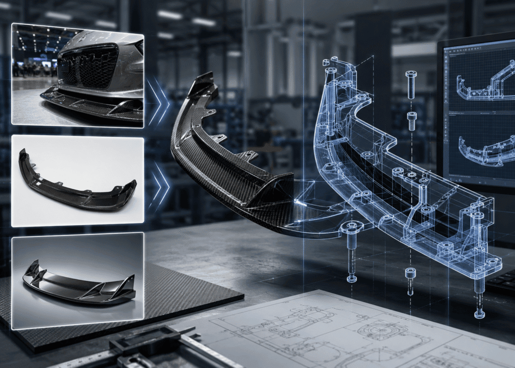
A brand owner sends three photos to a factory: a front three-quarter shot from a trade show, a competitor’s product listing image, and a rendering from a designer. The message reads: can you make this, and how much?
A photo defines intent. It does not define geometry. A capable factory can build something that looks like the picture. Building something that installs is a different problem requiring different information. That distinction is why product photos are not enough for carbon fiber development, and it is the most common reason a custom carbon fiber product development project stalls after the first sample.
What follows is what a photo can and cannot carry, what data actually moves a project forward, and what to do when you have none of it yet.
What a Product Photo Actually Tells a Carbon Fiber Engineer — and What It Hides
A photograph is a reliable record of intent. It communicates proportion, silhouette, weave direction, and gloss expectation. For carbon fiber product design, that is real input — it tells our engineers what the part is supposed to feel like on the vehicle.
It cannot carry the constraints that determine whether the part bolts on.
| Information the part depends on | Visible in a photo | Consequence if missing |
| Outer surface form and proportion | Yes | — |
| Weave direction and finish expectation | Partially | Cosmetic mismatch across a batch |
| Rear-side reinforcement and rib layout | No | Panel flex, cracking at load points |
| Factory mounting points and clip type | No | Part cannot be secured |
| Vent and duct internal depth | No | Blocked airflow, hidden interference |
| Edge gap targets against adjacent panels | No | Uneven gaps, visible misalignment |
| Ground clearance and approach angle | No | Scraping, field damage |
| Interference zones with lamps, bumper, fender | No | Part physically will not seat |
| Wall thickness and laminate schedule | No | Wrong weight, wrong stiffness |
Appearance is the result of a part. Mounting structure is the constraint on it. Engineering starts at the constraint and works outward, never the reverse. That is why appearance photos cannot replace engineering design, and every carbon fiber fitment failure we are asked to diagnose traces back to a project where the outer surface was frozen first and the mounting logic was reverse-fitted afterward.
On premium programs the constraint set is unforgiving. On one closed-panel roof assembly we engineered, the specification held the gap between the closed doors and the main body to within 1mm across the full closure line. That is not reachable by matching a photograph. It is reachable by controlling geometry, resin cure shrinkage, and carbon fiber tooling strategy from the first review.
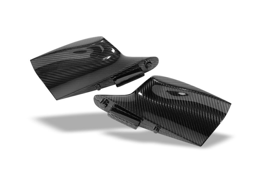
Why Carbon Fiber Manufacturers Need CAD Data
There is a mechanical reason behind the request, and it is worth understanding so it does not read as a supplier stalling.
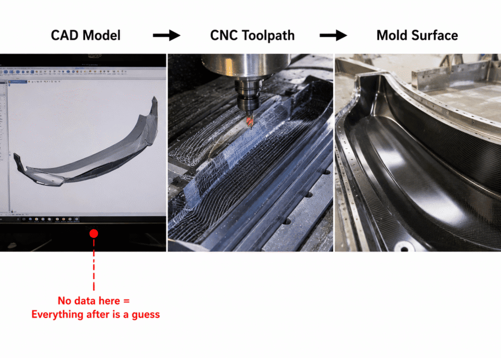
A mold surface is machined directly from a digital model. CNC toolpaths are generated from that model. Nothing in that chain accepts a JPEG. When geometry is absent, carbon fiber mold development does not pause — it proceeds on estimation, and the estimation stays invisible until the first part leaves the tool.
Composites raise the stakes. In metal fabrication the material exists before the part, and a stamped panel can be adjusted after forming. In composites, the material and the part are created in the same cure cycle. Layup sequence, wall thickness, fiber orientation, and shrinkage are all locked into the tool. A dimensional error is not a fixture adjustment; it is a mold modification.
A mold is cut from data. When the data is missing, it is cut from an assumption — and that assumption surfaces on the first fitment trial, after the tooling money is spent.
Once geometry exists, a carbon fiber engineering review has something to work on. Our team runs a carbon fiber DFM review against the model looking for named failure modes: draft angles too shallow to release the cured part, sharp internal radii where fabric bridges instead of conforming, and low-lying zones where resin pools and adds both weight and surface defects. The same review fixes carbon fiber CAD design decisions that are expensive to revisit later — split lines, whether rear-side sliders are needed for safe demolding, and whether the part requires a single-sided or double-sided mold.
None of those checks run against a photograph.
What Information Is Actually Needed for Custom Carbon Fiber Products
Buyers regularly ask what data is needed to quote a custom carbon fiber part with real accuracy. The answer is tiered, and most projects do not start at the top tier. That is normal.
| Data tier | What you have | How far the project can go | What still has to close |
| Tier 1 — Complete | 3D CAD (STEP / IGES / X_T / native), 2D drawings, adjacent-part data, tolerance spec | Directly into DFM review and tooling quotation | Surface finish standard, volume |
| Tier 2 — Workable | Original OEM part, physical prototype, donor vehicle available, or existing scan data | Scanning or reconstruction, then full engineering review | Scan accuracy verification, structural definition |
| Tier 3 — Photos only | Reference images, renderings, competitor shots | Feasibility discussion, process direction, budget range | All geometry — data acquisition required before tooling |
If you are at Tier 3, this is the practical answer to what information is needed for custom carbon fiber products and what to prepare before requesting a carbon fiber mold quotation:
• Multi-angle photos, including close-ups of the rear face and the mounting area
• Vehicle make, model year, and trim or configuration code — mounting points differ across trims on the same platform
• Photos of the factory installation area on the actual vehicle
• Functional intent: cosmetic only, aerodynamic, load-bearing, or thermal
• Target quantity and finish standard (gloss clear coat, matte, painted)
• What is wrong with the part you are replacing, if anything
Our engineering team turns around a technical feasibility assessment on this input within 24 hours, covering material direction, structural risk, and cost optimization. Tier 3 is not a dead end. It is a project that is not yet ready for tooling, and knowing that on day one is worth more than a fast quotation that gets revised three times.
No CAD Files? The Path Forward Still Exists
The real question behind most of these conversations is can carbon fiber parts be made without CAD files. Yes, routinely. A large share of custom carbon fiber parts in the aftermarket begin with no digital data at all.
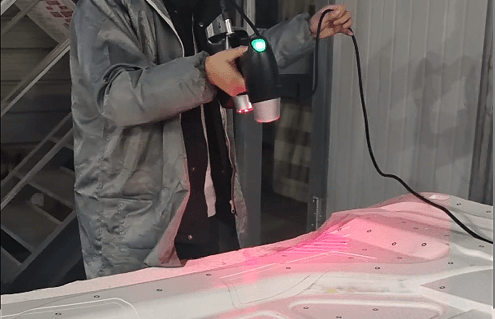
Three routes close the gap: reverse engineering carbon fiber parts from an original OEM component, on-site scanning of a donor vehicle, or rebuilding geometry from a physical sample you supply. 3D scanning for carbon fiber parts captures the condition the vehicle actually presents, not the condition a drawing claims. We expanded these scanning operations globally in 2024 and run dedicated teams that travel to the vehicle when the vehicle cannot travel to us.
Scanning is the start of the engineering work, not the end of it. Point cloud data has to be cleaned, converted to surfaces, rebuilt as a parametric model, given structural definition, and put through DFM review before anything is cut. Anyone promising that a scan guarantees a first-time-right sample is selling certainty they cannot deliver. What scanning removes is guesswork in the geometry, which is how 3D scanning reduces carbon fiber fitment problems — fewer correction loops, not zero risk.
Scan quality is its own discipline. Low-resolution equipment, inconsistent method, and unregistered reference points produce files that look complete and are not. We have rebuilt projects where the client’s own scan data was the root cause of the fitment failure, and why scan accuracy determines the outcome is worth reading before you commission scanning anywhere.
The Custom Carbon Fiber Product Development Process, Step by Step
Each stage of a structured custom carbon fiber product development process retires one category of risk:
1. Engineering review and data assessment — removes the risk of starting on a false premise
2. Data acquisition (scan, sample, or donor vehicle) — removes surface deviation
3. CAD design and structure definition — removes missing mounting points, thickness, and reinforcement; where a part carries load, this is also where in-house FEA has something real to analyze
4. DFM review — removes demolding lock-out, fabric bridging, and resin pooling
5. Tooling strategy (split lines, sliders, mold material and thermal stability) — removes downstream mold modification cost
6. Carbon fiber prototyping and fitment validation — removes first-article installation failure
7. Process selection and production — removes batch-to-batch inconsistency
Fitment risk is eliminated at steps 1 and 6. It is not inspected out at step 7. A supplier who compresses or skips steps 1, 4, and 6 quotes lower and delivers later.
This is the working difference between a shop that reproduces an outer surface and an engineering partner. Suppliers competing on tooling price fold the review stages into the quotation and find the problems during sampling, at which point the cost reappears as mold modification and schedule slip. Our 58-day concept-to-sample workflow holds because the data and review stages happen up front — complete input is what makes a compressed timeline realistic rather than optimistic.
For carbon fiber OEM ODM programs the same discipline governs long-term stability. Once a first sample is validated, the process is documented into a standard SOP with control points at each step, which is what keeps part fifty consistent with part one. The carbon fiber manufacturing process selected at step 7 — autoclave prepreg, HP-RTM, compression molding, or infusion — follows directly from the structural and volume decisions locked at steps 3 through 5.
Where the Cost of a Photo-Only Start Actually Lands
Skipping data acquisition saves a few days and a scanning fee. It does not remove the cost. It relocates it.
Ask any distributor why aftermarket carbon fiber parts do not fit properly and the answer sits downstream of the same decision. Quotations get revised because the scope was never real. Molds get modified. Samples ship twice. The launch window closes. Installers bill extra labor for parts that need trimming to seat. Distributors absorb the returns. The brand that commissioned the part carries the reputation damage, not the factory that made it.
Procurement leads read this as total landed cost. Engineering teams read it as rework hours. Brand owners and startup founders read it as a product review problem. Body shops and installers read it as an hour that should have been twenty minutes. One root cause, four ledgers.
Front-loading data is not an added expense. It moves uncertainty out of production, where it is expensive, and into engineering, where it is cheap.

Bring the Data, Not Just the Picture
Photos are a legitimate starting point. They are not an input to tooling. Projects that reach market on schedule are the ones where somebody asked early — what do we actually not know yet — and then closed those gaps deliberately through scanning, reverse engineering, or sample-based reconstruction.
Send what you have, however incomplete. A carbon fiber engineering review will tell you what is missing and what it takes to close it, before anyone quotes a mold. That conversation is worth more than a price.
Frequently Asked Questions
Can you develop a custom carbon fiber part from photos only?
We can start from photos. Feasibility, process direction, and a budget range are all possible. We cannot cut tooling from them. Before mold work begins, geometry has to come from CAD, a scan, or a physical reference part.
What if I don’t have the original part or access to the vehicle?
Then the first task is deciding how to obtain geometry. Options include sourcing an OEM component for reverse engineering, sending a scanning team to wherever the vehicle is, or building from a physical prototype you supply. Which route makes sense depends on the part and the market.
Does 3D scanning guarantee perfect fitment?
No, and treat any supplier who says otherwise carefully. Scanning removes guesswork from the surface geometry. Fitment still depends on CAD reconstruction quality, mold accuracy, cure shrinkage control, trimming, and first-article validation on the actual vehicle.
How much data do you need before you can quote accurately?
Enough to know what the part attaches to. A quotation based on photos alone is a range, and it will move. A quotation based on validated geometry, a defined finish standard, and confirmed volume is one you can budget against.
We already have scan data from another vendor. Can you use it?
Usually, but we verify before building on it. We check resolution, coverage of the mounting areas, and reference registration. If the data has gaps in the regions that determine installation, rescanning that area is faster than working around it.