Most procurement teams open with the wrong question about the carbon fiber manufacturing process: “which one is best?” There is no best. Autoclave-cured prepreg carbon fiber isn’t better than carbon fiber compression molding — it’s better at some things and worse at others. Treating one route as universally superior is the most expensive mistake we see B2B buyers make, because it pushes them to overpay for parts that never needed the premium, or to under-build the ones that did. Sound carbon fiber process selection starts from your product, not the process: your annual volume, your required finish, and your structural load. Get those three right and the process picks itself.
There’s No “Best” Process — Only the Right One
Three variables decide nearly every composite program: production volume, appearance, and structural strength. Knowing how to choose a carbon fiber manufacturing process means weighting those three honestly for your part — not defaulting to the most prestigious-sounding route.
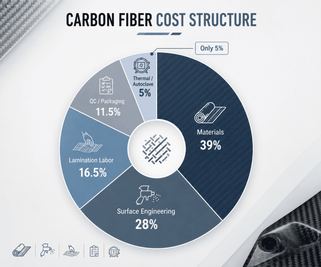
Look at where the money actually goes and the point gets sharper. In a typical finished part, raw materials — face and structural carbon plus core — run about 39% of the quote, and multi-stage manual sanding, leveling and polishing eat roughly 28%. Autoclave energy and curing, the step buyers fear most on a quote, is around 5%. So the cost isn’t hiding in the word “autoclave.” It’s in material grade and surface class. Pick the process your volume and finish actually demand, and stop paying for a label.
Materials ≈ 39% of cost. Surface engineering ≈ 28%. Autoclave curing ≈ 5%. Your cost lives in material and finish — not in the word “autoclave.”
The Four Core Processes at a Glance
Four routes, each built for a different job:
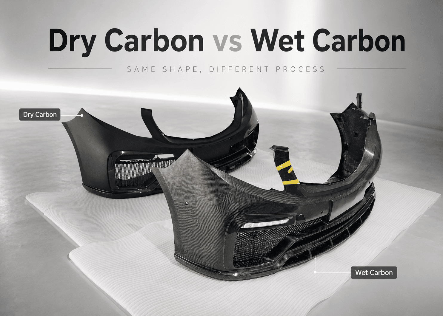
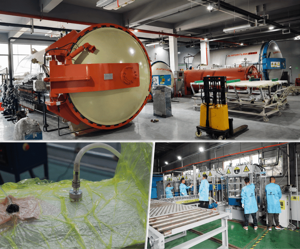
- Autoclave carbon fiber (Dry Carbon): prepreg cured under vacuum and pressure — for us, at least −0.1 bar, then 150°C for 150 minutes under 6 bar, with demolding kept below 80°C. Lowest void content, cleanest weave, highest strength-to-weight; higher cost, lower throughput.
- Vacuum infusion carbon fiber (Wet Carbon): dry fabric infused under vacuum. Lower tooling and energy cost, solid structural performance, the faster route to price-driven share.
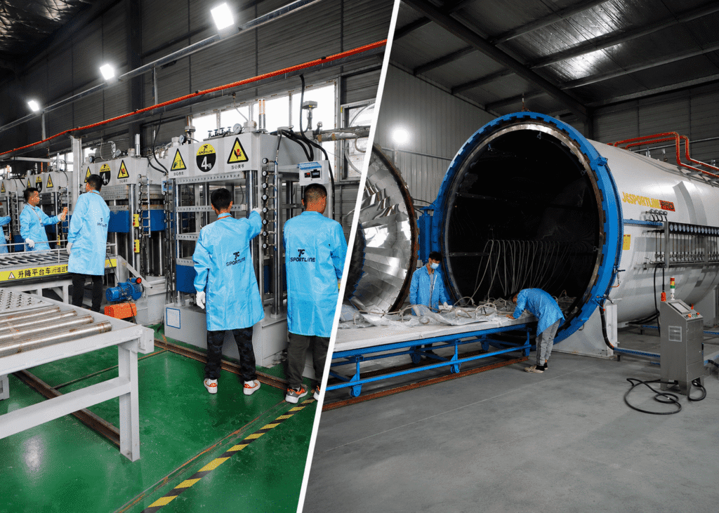
- Carbon fiber compression molding: prepreg pressed in a matched mold at roughly 7–20 MPa — repeatable, high-volume, tight dimensions.
- HP-RTM carbon fiber: resin injected at high pressure into a closed mold — structural parts at automotive volumes.
| Process | Volume fit | Appearance | Strength | Relative cost |
| Autoclave (Dry Carbon) | Low–mid | Best | Highest | High |
| Vacuum infusion (Wet Carbon) | Mid | Good | High | Medium |
| Compression molding | High | Consistent | High | Low per unit |
| HP-RTM | High | Good | Highest (structural) | Tooling-heavy |
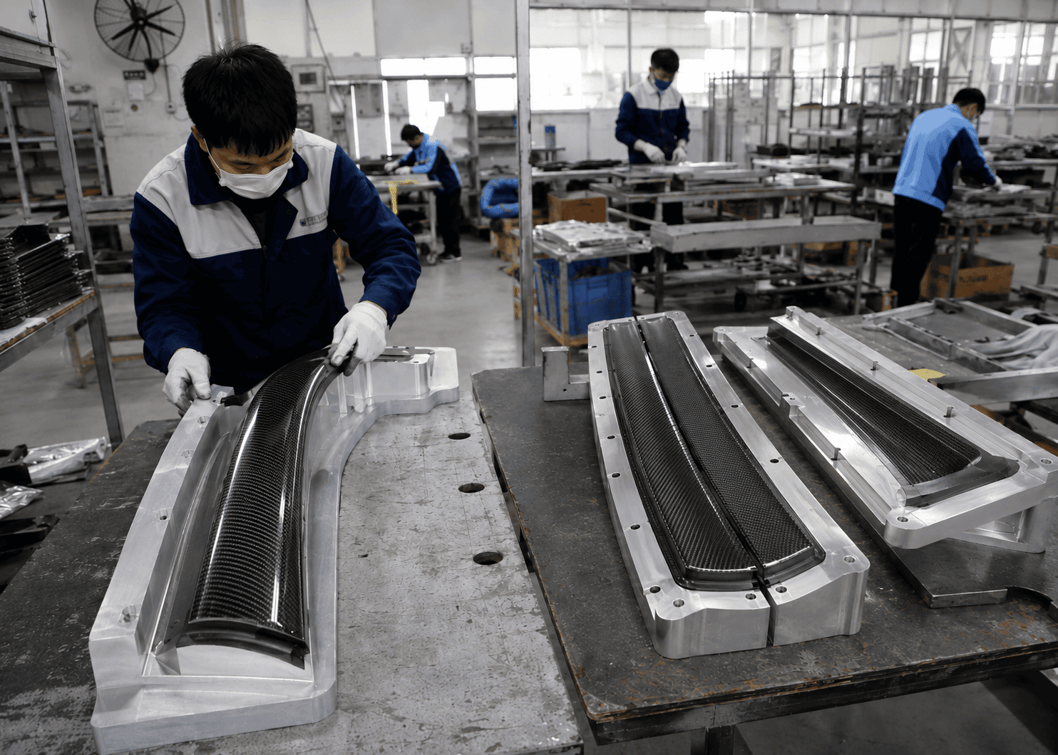
Tooling-based parts usually start at an MOQ of 30–100 units, after a prototype or small-batch validation stage. Which mold you build for each route matters as much as the route itself — carbon fiber compression molding and the mold type you choose set both your unit cost and your achievable tolerance.
Matching Process to Production Volume
This is where matching carbon fiber process to production volume stops being an engineering call and becomes a supply-chain one.
At low volumes, speed and tooling cost decide it. A low volume carbon fiber prototyping process built on 3D-printed plugs and high-density resin molds — about 200 cycles at roughly one-fifth the cost of metal tooling — lets you validate fit before committing capital. On a UK championship racing project with no slack in the deadline, we used 3D printing to compress the schedule, re-tuned the mounting positions across several iterations until the fit was exact, and delivered in roughly 60 days. Hard tooling would have blown the timeline and the budget.
At the other end, the best carbon fiber process for high volume production is compression molding or HP-RTM, where matched tooling holds dimensions across thousands of parts. That’s also which carbon fiber process for OEM mass production programs standardize on.
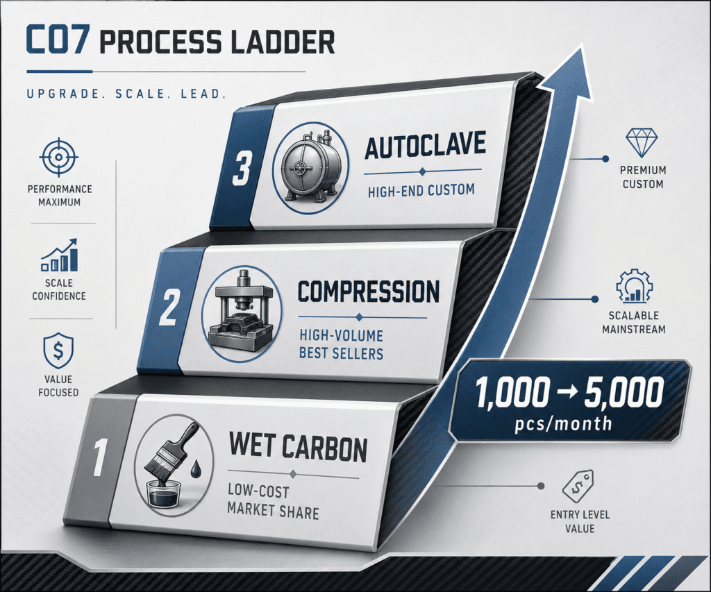
You rarely pick just one. A Tesla-focused trader was bleeding account health to stockouts because demand outran capacity. We layered three processes onto a single product line: autoclave for their high-end, own-brand custom range; compression molding for the high-volume bestsellers; wet-carbon vacuum parts to grab price-driven share. Spoiler output climbed from 1,000 to 5,000 units a month — same product family, three processes, one supplier.
One product line, three processes: spoiler output 1,000 → 5,000 units / month.
Matching Process to Appearance
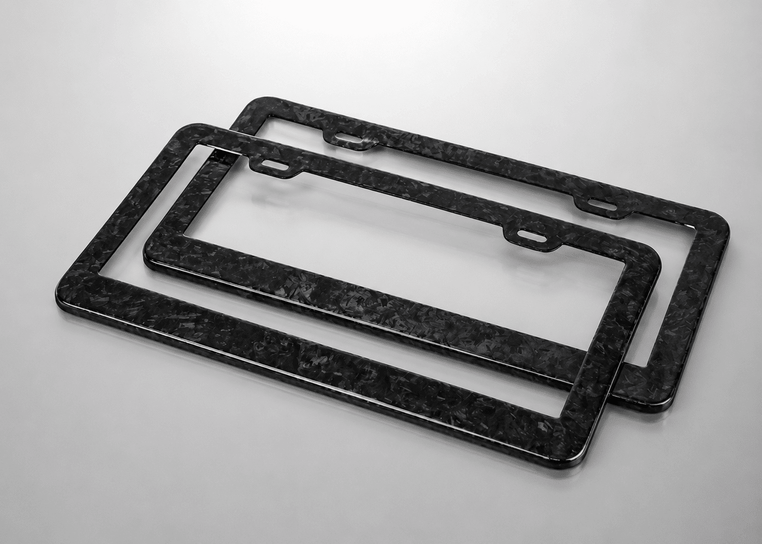
For consumer-facing automotive parts and premium water-sports gear, the finish is the product. Dry carbon vs wet carbon is partly a surface decision: dry carbon delivers the crisp, high-definition weave, and the upgrades cost real money — forged adds about 30% over standard carbon, gloss black about 20% over matte. Designers chasing a carbon fiber process for Class A surface finish should budget that ~28% surface-engineering share in from day one, not wish it away.
Consistency is where most suppliers quietly fail. A global brand’s UK team was re-painting and polishing China-made carbon intakes in their own warehouse — surfaces arrived scratched and under-gloss, so they were paying finished-goods prices for semi-finished parts. We rebuilt the repair flow to their standard: moved from wet to a dry-sanding line, ran paint-adhesion and hardness tests, matched the paint and consumables down to polishing wax and grit, and pre-embedded the hardware. Their local post-processing cost fell about 80%, and the parts stopped getting reworked on arrival. Finish also has to survive the field — ours is validated to 1,500 hours of yellowing resistance, which is the difference between a one-time sale and a consistent, repeat-order product line.
Matching Process to Structural Strength
Carbon fiber is anisotropic — strength comes from ply orientation, not the material alone — which is exactly why structural engineers can’t spec it like aluminum. A carbon fiber process for structural strength has to consolidate the laminate at low void content and let you put fiber where the load actually is.
The data settles the argument. In our metal-versus-composite study of a roof front cross-member, an HP-RTM part — T300 unidirectional and twill, six plies, 3.5 mm — came in 53.7% lighter than the stamped-steel assembly (0.718 kg vs 1.2 kg) while lifting bending stiffness from 152 to 284.3 N/mm and peak bending load from 1,018 N to 2,681 N. Constrained first-mode frequency rose from 76.8 Hz to 122.7 Hz. That’s the gap between a cosmetic part and a structural one, and it only shows up when you test it on real equipment instead of trusting a datasheet. The autoclave vs compression molding carbon fiber question lands here too: autoclave consolidation suits the highest-performance structures, HP-RTM carries that strength into volume.
HP-RTM roof cross-member vs stamped steel: 53.7% lighter (0.718 kg vs 1.2 kg) · bending stiffness 152 → 284.3 N/mm · peak bending load 1,018 N → 2,681 N.
A composite surfboard program makes the same point in another industry. The client had been stuck for ten years. We upgraded them from infusion wet carbon to a hot-press-plus-compression combination — appearance from one, cost-efficiency from the other — went from a multi-block mold to one-piece forming, swapped stainless hardware for titanium, and held the board to 8 kg. Six months later they were running 1,000 sets a month.
Why One Process Can’t Serve Every Product
This is the line between a single-process workshop and an engineering partner: a workshop makes your product fit its one process; we fit the process to your product. Running autoclave, infusion, compression and HP-RTM under one MES-scanned SOP system is also what makes batch consistency physically possible. A European tuning brand had samples that looked perfect and production that didn’t — weave drift, gloss variance, color shift between batches, and a rising aftersales rate. We locked the approved sample as the sole production standard, fixed the 3K/12K layup and orientation in the SOP, added IPQC and FQC checkpoints and a small-batch validation gate. Aftersales fell; orders grew about 30%. A German OE-spec client whose previous suppliers swung between 10 and 15 kg per part got consistency only once layup was designed in from R&D — not inspected in at the end. That’s the heart of our multi-process carbon fiber solutions: the process serves the product.
Before any of this, a DFM review and feasibility study fix the process, BOM and cure cycle up front — which is why a carbon fiber manufacturing process for automotive parts can hit its cost target and its tolerances at the same time, instead of trading one for the other.
Conclusion
There is no best carbon fiber manufacturing process — only the one that fits your volume, your finish, and your load. The supplier question that actually protects you isn’t “do you run an autoclave?” It’s “can you run several processes under one quality system, and will you put mine on the right one?” If the answer is no, you’ll pay for it later — in rework, in stockouts, or in a part that’s heavier and weaker than it ever needed to be.
FAQ
1. What manufacturing processes does JCSPORTLINE offer?
We support multiple composite processes, including prepreg autoclave curing, oven curing, vacuum infusion, compression molding, forged carbon molding, and project-specific hybrid process routes. The right process is selected according to strength, appearance, tolerance, cost, and production volume.
2. Which process is best for faster production and higher output?
Compression molding is usually the best option when a project requires high repeatability, faster cycle time, and larger-volume production. However, it requires suitable product geometry, mold investment, and engineering feasibility review before confirmation.
3. Can you make OEM-level matte or special surface finishes?
Yes. We can support gloss, matte, forged carbon, colored carbon, gloss black, and other project-specific finishes. For matte finishes, we can control gloss level according to client requirements and validate surface stability through production and QC standards.
4. Can JCSPORTLINE provide CFD simulation for custom carbon fiber rear wings?
Yes. JCSPORTLINE can provide CFD simulation and aerodynamic validation based on project requirements. This helps evaluate airflow behavior, pressure distribution, downforce balance, and aerodynamic efficiency before prototyping or production. CFD support is available as an additional engineering service and may be charged separately depending on project complexity and scope.
5. What dry carbon processes can be used for carbon fiber hydrofoil surfboards?
JCSPORTLINE can support both compression molding and hot press forming for dry carbon hydrofoil surfboard projects. Compression molding is suitable for structural strength, repeatable production, and stable consistency, while hot press forming can provide better surface control and cleaner carbon fiber weave appearance.