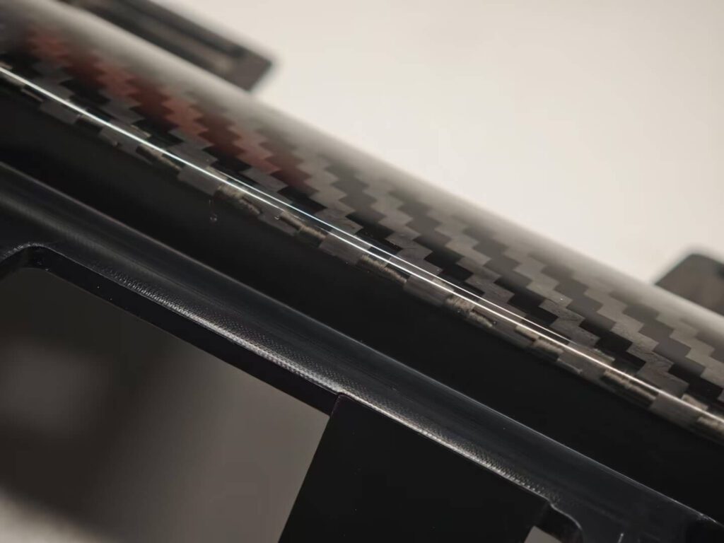
Most conversations about carbon fiber interior trim start with the weave, the gloss, and a photograph of a finished console. For an OEM programme, none of that is the decision. The decision is what happens to the component that already exists — tooled, validated, and running down a production line.
That constraint is what makes carbon fiber overlay bonding worth understanding. It gets dismissed as decorative work, one step above a vinyl skin. That reading is wrong. Overlay bonding answers a specific and very common condition: the base component is frozen, the assembly interfaces cannot move, and the brand still needs a visible material upgrade for a sport-trim or special-edition variant. Under that condition, bonding a precision carbon shell onto the released part is not the compromise. Rebuilding the part is.
What follows is how the process runs on our floor, where it belongs, where it does not, and what separates an OEM-grade result from a piece that photographs well once.
What Carbon Fiber Overlay Bonding Actually Is — and What It Is Not
Two routes exist for combining carbon fiber with an existing plastic or metal component. They are not a basic version and a premium version of the same thing. They answer different questions.
Route A — Overlay: a carbon shell bonded onto the existing part
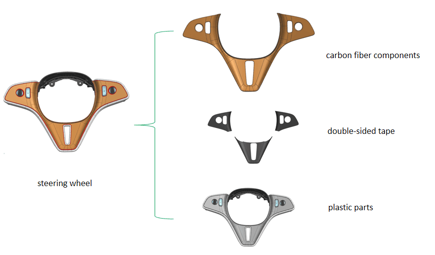
The original component stays exactly as it is. A custom-formed carbon shell bonds to its outer surface with automotive-grade acrylic foam tape. Clip geometry, switch apertures, sensor pockets and mounting datums are untouched. This is what surface bonding means in practice, and it is the route most carbon fiber trim programmes take.
Route B — Replacement: the carbon part becomes the part
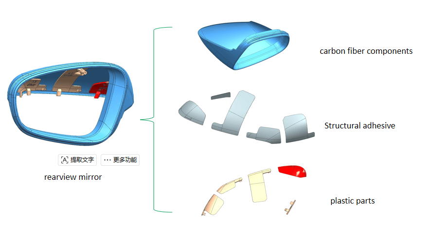
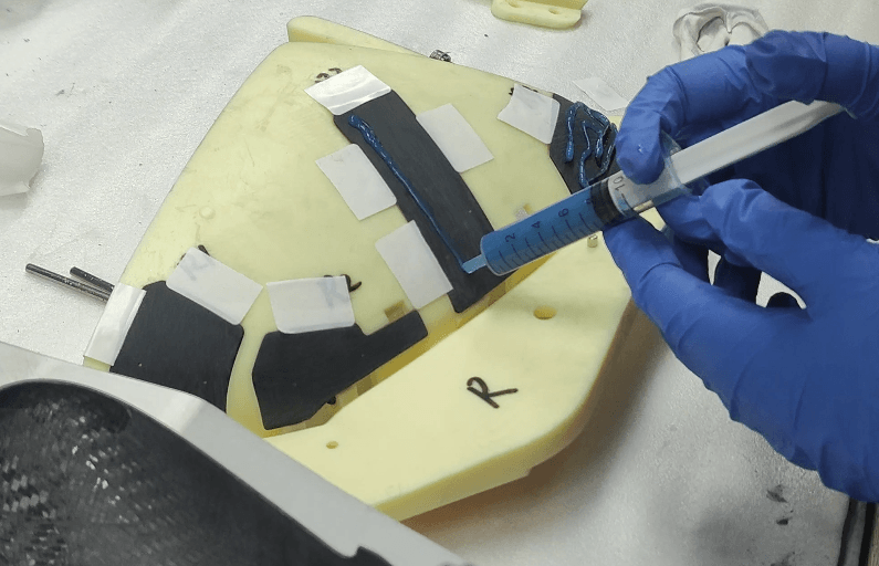
The carbon component fully replaces the original and carries its function. Where a clip block, a complex snap-fit, or a geometry carbon cannot form is required, that region is split out, kept in its original plastic or metal design, and joined to the carbon part using a two-part structural adhesive bonding system. The whole operation runs on dedicated fixtures holding both halves in position through cure.
One question separates them: does the carbon need to carry the part’s function, or only its appearance?
| Overlay Bonding | Part Replacement | Full Redesign | |
| Original structure | Unchanged | Replaced, clip zones retained | Redesigned |
| Tooling scope | Shell tooling only | Shell + fixture tooling | New tooling, full set |
| Development load | Fit validation | Fit + function validation | Structural + function + vehicle validation |
| Re-validation on vehicle | Interface only | Function and interface | Full |
| Typical parts | Trim strips, mirror caps, wheel bezels | Covers with load or clip duty | Structural or weight-target parts |
| Best fit | Derivative and sport-trim variants | Function-carrying visible parts | Ground-up programmes |
Why OEM Programmes Choose Overlay Over Rebuilding the Part
On a production vehicle the base component is not a shape. It sits inside a tolerance chain, a clip retention scheme, a switchgear or airbag interface, and a set of gap-and-flush targets signed off months earlier. Replacing the part reopens all of it.
The expensive part of rebuilding is not the tooling invoice. It is the validation calendar. A sport-trim variant of a running model has no room to reopen structural sign-off for a carbon fiber car interior package. Overlay bonding collapses the engineering problem to a single variable — the accuracy of the bonding surface. Nothing upstream of that surface changes.
This settles the question procurement teams ask first: does carbon fiber interior trim require modifying original structure. On the overlay route it does not. No drilling, no clip relocation, no revision to the released component drawing.
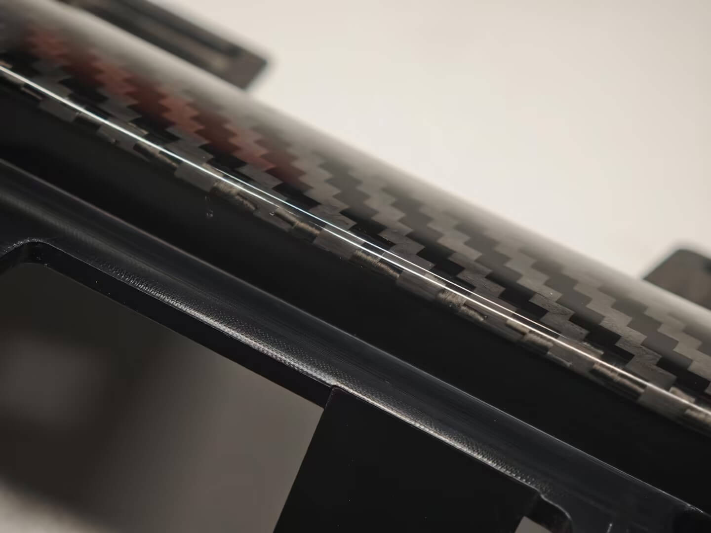
The number that makes this work is the stack height. The carbon shell, the adhesive and the double-sided tape together stay under 1mm. That is what keeps the upgrade inside the existing packaging envelope. A trim panel sitting a millimetre proud of its neighbours is a gap-and-flush failure, not a styling choice — and it is exactly what happens when a shell is formed too thick or the bond line is left uncontrolled. Holding the full stack under 1mm is a design requirement built into the shell tooling, not something corrected at assembly.
Sourcing leads get a shorter path to a firm unit price. Interior and release engineers get a change scope small enough to defend in a design review. Supplier quality engineers get a variant that does not reset the PPAP conversation on the base part.
When the base component is already released and validated, the strongest engineering decision is the one that changes the fewest variables. Overlay bonding changes one.
Inside the Process: How a Carbon Overlay Is Actually Bonded
Both routes run to a fixed sequence. The detail matters because overlay failures almost never originate in the adhesive — they originate in what was done to the surfaces before the adhesive arrived.
Overlay route: surface preparation decides the bond
Every step in the sequence exists to remove a specific failure mode. Bond strength is decided by surface preparation, not by the adhesive, which is why more of the process sits before the adhesive than after it.
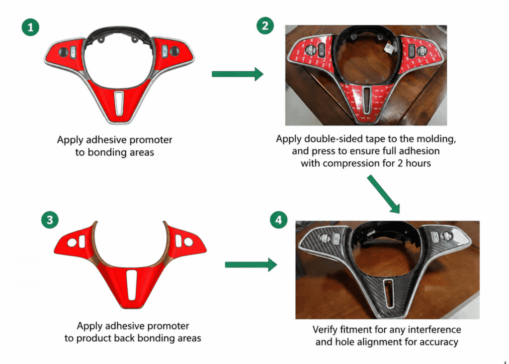
Clear all dust and contamination from the bonding zone on the base component, then clean it with alcohol. Sand any paint accumulation or raised points on the back face of the carbon shell until it runs flat — a shell that rocks on a high spot never seats evenly. Clear that face of sanding dust and clean it with alcohol as well; abrading a surface and then bonding over the residue is worse than not abrading it at all. Apply the specified adhesion promoter to both prepared faces — the promoter is matched to the substrate, and substituting it is not a cost saving. Lay the tape following the part contour, then press it down over two full passes so it conforms to curvature instead of bridging across it. Dry-fit the assembly and confirm there is no interference and that hole positions are even and correct.
That trial fit before final bonding is the last point at which a geometry problem costs nothing.
Replacement route: fixtures define the geometry
The plastic component’s bonding face is abraded and cleaned. The matching area on the carbon part is abraded and cleaned to the same standard. Both are located on their fixtures. Adhesive is applied, the assembly is closed, and it cures under fixture constraint before demolding. Fixtures are not handling aids here — the fixture is the dimensional standard, and the joint is only as accurate as the locating scheme holding it.
These are the carbon fiber overlay bonding process steps in functional form, and they describe the carbon fiber steering wheel trim manufacturing process as accurately as they describe any bezel or cover we run.
The double-sided tape vs structural adhesive for carbon fiber choice follows from route selection. Tape carries a decorative shell that transfers no load. Structural adhesive carries a joint that does. Specifying one where the other belongs is the most common error we see in incoming project data.
Two press-down passes is not a cosmetic instruction. It converts surface contact into full-area adhesion across a curved part. It is specified as two because an operator under time pressure will otherwise do one.
Where Overlay Bonding Fits — and Where It Doesn’t
Overlay bonding is not a general substitute for carbon fiber manufacturing. Treating it as one puts the wrong process on the wrong part.
| Part type | Recommended route | Reason |
| Interior trim strips, console bezels, door inserts | Overlay | Appearance-led, stable bonding face |
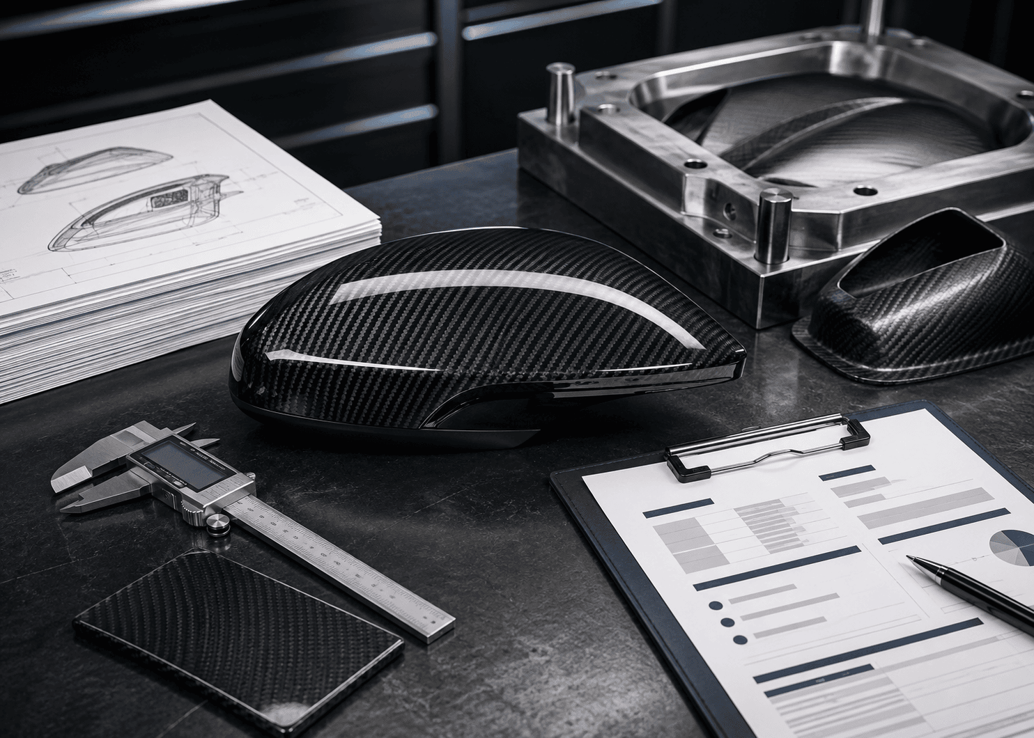
| Carbon fiber mirror caps | Overlay | Contoured but non-structural, well suited to shell bonding |
| Steering wheel decorative panels | Overlay | Fixed geometry, appearance-critical, function retained by base part |
| Vent surrounds, switch panels | Overlay | Tight apertures better held by the original part |
| Covers with clip or retention duty | Replacement | Carbon must carry function |
| Load-bearing or weight-target components | Neither — mould directly | Requires an engineered layup, not a bonded skin |
| Large single-curvature exterior panels | Mould directly | Bond line length and thermal behaviour work against overlay |
Carbon fiber interior trim kits are developed as matched sets for the same reason. Weave direction, gloss level and finish get specified once across the whole set, so the cockpit reads as one design intent rather than several suppliers’ interpretations of it. We run this alongside our broader custom carbon fiber parts development, and the set-level specification is what separates an OEM package from a collection of accessories.
What Separates a Sample from a Production Run
Any competent workshop produces one excellent overlay part. The OEM question is whether set 2,800 in a 3,000-set programme matches set four.
Four things get inspected, and all four are process outputs rather than material properties:
- Weave alignment. Fixed at cutting. Fibre direction is set against a part datum, not judged by eye at layup.
- Gloss stability. Controlled in coating and cure, not corrected in polishing.
- Batch-to-batch appearance. Weave depth and clarity at close interior viewing distance.
- Fit accuracy. Verified on a fixture, not against the previous good part.
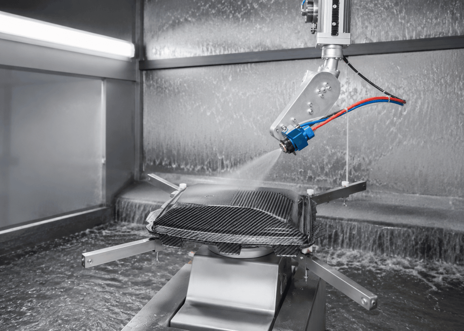
The third point is where dry carbon stops being a marketing word. A carbon fiber interior panel is viewed from under a metre, in changing light, every day. Wet lay-up surfaces show resin variation and weave distortion at that distance. Prepreg arrives with its resin ratio fixed at the material supplier, and our autoclave cycle for these shells runs at 150°C for 150 minutes under 6 bar, with demolding controlled below 80°C to prevent thermal distortion. Fixed resin content plus a controlled cure is what makes the surface repeatable — which is why dry carbon is specified for premium interiors, and why how to ensure carbon fiber weave consistency in mass production is a materials decision before it is a quality decision.
For batch consistency for carbon fiber interior trim, four questions belong in the RFQ: Is fibre orientation fixed by a cutting datum? Is gloss measured or judged? Is fit checked on a fixture? Are the process parameters fixed and documented, or set by the operator? A supplier who cannot answer those four questions is describing an outcome rather than controlling one. That is the working test of an OEM carbon fiber interior trim supplier, and it is the same discipline that governs our mass production lines.
Case Study: A Three-Part Interior Programme for a Chinese Premium EV Brand
A Chinese premium EV brand was preparing a sport-trim variant of a production electric SUV and needed a visible material upgrade without touching the released interior architecture.
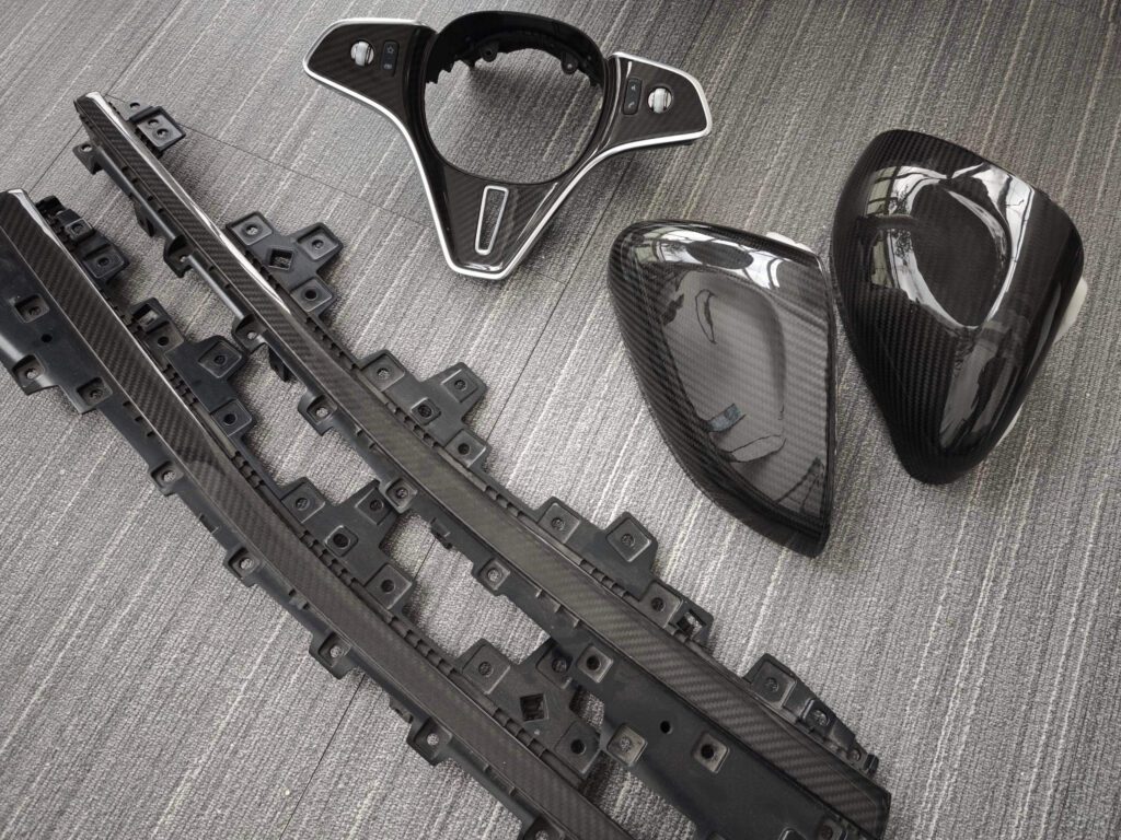
Three parts were in scope: an interior trim strip, carbon fiber mirror caps, and a carbon fiber steering wheel trim panel, developed and supplied as one matched set under an OEM programme. Because the base components were already in production, the overlay route was selected — precision-formed dry carbon shells bonded to the existing parts, with no change to the original structure.
The programme delivered 3,000 matched sets. Across those batches, weave texture, gloss level and fit accuracy held to the standard set at first-article approval. That outcome reflects this programme’s specific parts, materials and volume rather than a universal result. Further detail on our OEM carbon fiber interior trim development work is available on the project page.
Frequently Asked Questions
Will an overlay-bonded carbon trim stay bonded in service?
Bond performance is set by preparation, not by the adhesive alone. The sequence is fixed: clear all dust from both bonding faces, flatten the back face of the shell, alcohol-clean both surfaces, apply the specified adhesion promoter to both, and press the tape down over two full passes for complete contour contact. Where a joint carries any load, we specify structural adhesive with fixture cure instead of tape.
Does overlay bonding require changing the original part or vehicle structure?
No. The released component keeps its geometry, clips, apertures and mounting points. Only the visible surface changes, and the full bonded stack stays under 1mm so the part remains inside its original packaging envelope.
How do you hold the weave pattern across thousands of sets?
Fibre orientation is fixed at cutting against a part datum, shells are formed in matched tooling, and bonding position is set on fixtures. Each of the three is a control point rather than an inspection point.
Can overlay and replacement be combined in one programme?
Yes, and often they should be. Appearance-led parts take the overlay route; parts that must carry clip or retention function take the replacement route with structural bonding. Routes are chosen part by part, not programme by programme.
What do you need to quote an overlay project?
The 3D data or a physical sample of the base component, the target finish and weave, the parts in scope, and the annual volume. Volume drives the tooling and fixture strategy more than any other input.
Bringing a Carbon Interior Programme to Production
Choosing overlay bonding does not lower the standard. It moves the standard from the part to the bond line — to surface preparation, fixture accuracy and batch control. Programmes that understand this get a carbon fiber interior trim upgrade without reopening validation. Programmes that treat overlay as decoration get one good sample and an inconsistent production run.
JCSPORTLINE develops carbon fiber interior components as OEM and ODM programmes: part-by-part route selection, shell tooling, bonding fixtures, fixed process parameters, and volume delivery. Send us the base component data and the parts in scope, and our engineering team will return a route recommendation and a feasibility assessment.